Young, T. S., Teather, R. J., and MacKenzie, I. S. (2017). An arm-mounted inertial controller for 6DOF input: Design and evaluation. Proceedings of the 12th IEEE Symposium on 3D User Interfaces - 3DUI 2017, pp. 26-35. New York: IEEE. doi:10.1109/3DUI.2017.7893314 [PDF]
An Arm-Mounted Inertial Controller for 6DOF Input: Design and Evaluation
Thomas S. Young1, Robert J. Teather2, and I. Scott MacKenzie1
1York University, 2Carelton Universitytsyoung@gmail.com, rob.teather@carleton.ca,
mack@cse.yorku.ca
Abstract We designed a low-cost arm-mounted wearable 3D input device that uses inertial measurement units. The device is an alternative to tracking systems requiring fixed frames of reference. The device employs two inertial sensors mounted on the arm to derive a 3D cursor position through natural arm movement. We also explore three methods of selection, one entirely software based (dwell, holding the cursor in the target), one using a twist gesture, and one using a button. To address the paucity of research reporting human performance metrics, we quantify the performance of the device through a point-select experiment. Results indicate that throughput was 1.05 to 1.12 bits/s. In contrast, similar studies using conventional 3D trackers (e.g., NaturalPoint OptiTrack) report throughput ranging from 2.5 to 3.5 bits/s. However, error rates for the wearable input device were lower than with the OptiTrack system at 6.8% vs. 13.5%, respectively. A detailed analysis of system performance issues is provided along with design suggestions for future gyro-based input devices.Keywords: Point selection. Gyro controller. Inertial measurement units. 3D selection interface. Fitts' law.
Index Terms: H.5.2.1 [User Interfaces]: Human-centered computing—User studies; H.5.2.1 [User Interfaces]: Human-centered computing—Pointing devices
1 INTRODUCTION
With the advent of a new generation of commodity virtual reality (VR) head-mounted displays, such as the Oculus Rift, Samsung Gear VR, HTC Vive, and others, there is great potential for new applications in 3D interaction. Never before has this technology been so accessible to so many people. Yet interacting in 3D remains challenging. One problem is the availability of input devices.
While the mouse is ubiquitous in desktop computing, as yet, no standard universally accepted input device exists for 3D user interfaces. This is not for lack of trying on the part of researchers and hardware manufacturers, as numerous 3D input devices have emerged over the years. We group these (roughly) into in-air tracker-based devices and desktop devices. Tracker-based devices employ some form of tracking technology, e.g., electromagnetic, optical, or mechanical. In general, they are prohibitively expensive for end users, although recent entries like the Razer Hydra1 challenge this notion.
Common tracker devices include electromagnetic sensors such as the Polhemus Patriot2 and the NDI Aurora3 (descended from the well-known Ascension family of trackers), optical trackers like the NaturalPoint OptiTrack4 family of trackers, or VICON's optical trackers5. A major limitation of trackers (aside from cost) is the tendency to offer only a fixed frame of reference – tracking space is limited. Most also suffer from interference effects, notably occlusion with optical technologies.
Desktop devices such as the 3DConnexion SpaceMouse6, and the Logitech AirMouse7 leverage user familiarity with devices like a mouse. Despite employing mechanical tracking technology, devices like the Geomagic Touch8 (formerly the Phantom Omni) and the Novint Falcon9 – both haptic devices – are also desktop devices, or 3D mouse analogs. These devices ultimately yield a single 3D cursor position, with the addition of force feedback. While in some cases they offer superior performance to 3D trackers [4, 48], they still require a supporting surface to operate on, much like a mouse. Desktop devices are thus unsuitable for VR scenarios where the user is standing or walking. Head-mounted displays also occlude the device; thus, the user often cannot see the device. A comprehensive overview of 3D input devices is provided elsewhere [32].
We note that inertial measurement units (IMUs) – input devices based on accelerometers and gyros – can overcome the limitations of both tracker-based and desktop-based devices. They are inexpensive, require little setup, operate without supporting surfaces, and theoretically support unlimited space sizes if the user carries the device with them and relative motion is all that is required. If mounted on the body (Figure 1 depicts the setup used in our study), occlusion is not a problem either.

Figure 1: The wearable input device used in our study.
However, the input potential of such devices has been underexplored in 3D contexts compared to the mouse and 3D trackers [4, 48]. Although there is extensive research in the design of inertial-based human tracking devices, there are comparatively few empirical studies on their performance in fundamental tasks like point-and-select. To our knowledge, no previous study has evaluated 3D point-select performance of wearable IMU-based input devices.
Our input device uses a combination of six-degree-of-freedom gyro and accelerometer sensors. Each sensor reads its orientation and any acceleration experienced in three-dimensional space. The sensors are worn on the forearm and upper arm. Rotations in three dimensions about the shoulder and elbow are registered. The system is self-contained and unobtrusive. However, the device itself provides no means to indicate selection. Thus, we present a study evaluating the effectiveness of the device combined with three methods of selection.
Our contribution is threefold:
- We present the design and implementation of a low-cost wearable input device for 3D point-select tasks.
- We evaluate and quantify performance of the device using a 3D Fitts' law task.
- We provide a detailed analysis of performance issues and design considerations for future reference.
To our knowledge, our study is the first to study performance of wearable IMU-based input devices in the context of fundamental point-select tasks in a 3D environment. We employ a 3D extension of a standardized ISO methodology for evaluating pointing devices [15, 43]. The principle advantage of this approach is the consistency in Fitts' throughput between studies following the ISO standard, and this enables comparisons among studies [42]. Throughput also incorporates speed and accuracy into a single metric, and thus characterizes pointing performance better than metrics like speed or accuracy alone (between which there is a clear tradeoff) [26]. It is our hope that the results reported herein will provide a global sense of the relative performance of IMU-based devices in 3D environments.
2 RELATED WORK
2.1 Inertial Motion Tracking
There has been significant interest in inertial measurement devices by researchers in the design of tracking systems and in their implementation for user interfaces. Table 1 presents an overview of previous work in several areas of interest. Many of the studies use IMUs in smartphone or similar devices [16, 36, 45], or wearable devices [7, 9, 20, 38, 39]. Others look at the use of IMUs for full body motion capture [18]. As seen in the table, some studies evaluate performance in 2D Fitts' law contexts. While this invites comparisons with other 2D studies (for reasons described in Section 2.4), these results do not translate directly to 3D contexts [49]. We extend this body of research by providing (to our knowledge) the first experiment on 3D point-select tasks in a Fitts' law context using an IMU-based wearable device.
Table 1. An overview of research on inertial measurement units (IMUs)
1st Author [ref] User Study Task Summary Device Modality Jain [16] yes 2D pointing Comparison of distal pointing techniques Phone Hand held Rico [39] yes 1D Fitts Body based gesturing Head, foot, wrist sensors Wearable Lazewatsky [20] yes 2D pointing Human robot interaction Google glass Wearable Raya [38] yes 2D Fitts Mouse for children with cognitive physical impairments Forehead sensor Wearable Hincapie-Ramos [14] yes 2D pointing Raycasting for self-contained AR HMD GyroWand Handheld Prayudi [37] no N/A Design of an arm motion capture system - - Oakley [31] yes 2D Fitts Pointing with hands, wrist, fingers comparison Handheld, wrist Wearable, handheld Yun [53] no N/A Design, Kalman filter - - Bachmann [3] no N/A Design; MARG sensor - - Burstyn [7] yes 1D Fitts Pose dependent display device Wrist sensor Wearable Jung [18] no N/A Motion capture system design based on smart shoes Full body Wearable Yun [54] no N/A Position tracking, gait analysis Foot sensor Wearable Pietroszek [36] [35] yes 3D pointing Raycasting, SmartCasting Phone Handheld Calvo [8] yes 2D Fitts Remote finger based pointing Ring Wearable Teather [45] yes 2D Fitts Tilt position vs velocity control Tablet Handheld Skogstad [40] no N/A Comparison between optical and inertial tracking Xsens, OptiTrack Wearable, camera Solberg [41] no N/A Comparison between optical and inertial tracking Qualisys, Axivity Wearable, camera
2.2 3D Selection
There is a large body of work on object selection techniques in virtual 3D environments [2, 13, 17]. Most selection techniques can be roughly grouped into ray-based or virtual-hand. Our gyro-based device falls under the latter category, as it supports 1:1 control of a 3D depth cursor through arm motions, rather than ray-based remote pointing. However, unlike most virtual hand implementations, our cursor is decoupled (i.e., offset) from the physical position of the hand. This occurs because we use a desktop stereo monitor with the cursor "inside" the 3D scene; hence, the screen prevents physically touching objects. Implementations using a head-mounted display could instead couple the cursor position to the physical hand, but we note that previous evidence suggests little performance difference [44].
Liu et al. [21] compared aimed movements in the real world with movements in virtual reality. They observed significant temporal differences in both the ballistic and control phases. Movements in virtual reality were less efficient and on average twice as long compared to real-world movements. The correction phase in virtual reality was substantially longer, taking on average 6× longer than real-world corrections. Improvements in the correction phase in virtual reality were more efficient, but that was attributed to the inherent need for less correction in the real world. This speaks to a need for highly precise input devices and effective visual feedback, since the correction phase is guided by visual feedback.
Teather and Stuerzlinger conducted several studies [48, 47, 49, 50] on 3D selection in a Fitts' law context, first extending and validating the methodology for use in 3D contexts [48]. They applied their framework in studying the influence of visual aids [50], and pointing at screen-space projections of targets [47]. Other researchers have employed the methodology in studying selection in HMD contexts [22] and touching stereo displays [6, 11]. Based on these results, we modeled our task after previous work [47], which improves comparability with past results. This provides a better idea of the relative performance of IMU-based input compared to the mouse and 3D trackers.
2.3 Jitter and Latency
Latency is known to impact the effectiveness of pointing interfaces [27, 34]. Jitter, when significantly present, is also known to impact effectiveness [46]. We expect a similar impact on performance with our device (which exhibits noticeably higher latency than a mouse); hence, we discuss these effects briefly here. The effect of lag on human performance was investigated by MacKenzie and Ware [27]. It was observed that at the highest lag tested (225 ms) movement times and error rates increased by 64% and 214%, respectively, while throughput decreased by 46.5%. The effect was modeled as a multiplicative factor added to Fitts' Index of Difficulty (ID). Lag and frame rate in VR displays have also been studied previously [52], confirming the multiplicative factor. It was observed that low frame rates degrade performance and that error rates and movement times increase in depth movements as opposed to movements orthogonal to the axis of viewing.
In another study, latency and spatial jitter on object movement were examined using a NaturalPoint OptiTrack compared to a baseline optical mouse [29]. End-to-end latencies were 35 ms for the mouse and 70 ms for the OptiTrack. Latency had a much stronger effect than jitter. Large spikes in jitter significantly impacted 3D performance, particularly when jitter levels are approximately half the target size or greater [41].
2.4 Fitts' Law and Throughput
Selection tasks that involve rapid-aimed movements to a target are well-modeled by Fitts' law. Our experiment employs a 3D interpretation of the Fitts' law task described in the ISO 9241-9 standard [15, 43]. We now describe the evaluation protocol and calculation of the dependent variable called throughput. The ISO standard's reciprocal targeting task is depicted in Figure 2. The task ensures consistent difficulty within a circle of targets, as target distance and size are the same within a circle. The task can be further presented at varying depths for 3D pointing [48].
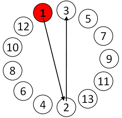
Figure 2: Two-dimensional Fitts' law task in ISO 9241-9.
The primary dependent variable of interest is throughput [23, 24], previously known as Fitts' index of performance [12]. Throughput incorporates selection speed and accuracy into a single metric through a post-experiment correction to the error rate (see below) and has been shown to compensate for the speed-accuracy trade-off [26]. Throughput (TP, in bits per second) is computed as the ratio of the index of difficulty (ID, in bits) and the movement time (MT, in seconds) computed over a sequence of trials:
| TP = ID / MT | (1) |
ID is calculated using movement distance, A (for amplitude), and target width, W. The Shannon formulation of ID is given as:
| ID = log2(A / W + 1) | (2) |
The ISO 9241-9 standard specifies calculating throughput using IDe rather than ID. This better accounts for the variability in target selections [23]. IDe is calculated as:
| IDe = log2(Ae / (4.133 × SDx) + 1) | (3) |
The Ae term is the effective distance a participant actually moved between targets, i.e., the average of the actual movement distances over a sequence of trials for a particular A-W condition. SDx is the standard deviation of selection coordinates projected onto the task-axis over a sequence of trials. Multiplying by 4.133 yields the so-called effective width (We), and adjusts the experimental error rate to a nominal value of 4%. This effectively normalizes error rates and strengthens comparisons of results between studies. Figure 3 depicts the calculation of Ae and We.

Figure 3: The effective index of difficulty (IDe) is calculated using the effective distance or amplitude (Ae) and the effective width of the target (We).
Fitts' law has been extended to two dimensions (see Figure 2) [25, 29] and three dimensions [10, 30]. In the 3D case, a direction parameter is included as a practical extension for common 2D tasks on a computer display [30]. We note that adding extra parameters in a regression analysis inherently improves the model fit for a given dataset [33]. Care must be taken to ensure that extensions to the model generalize to other results. The principle advantage of the approach proposed by Teather and Stuerzlinger [48] is that it "collapses" to a 2D task equivalent to mouse pointing and allows comparisons with a large body of 2D literature. It has also demonstrated consistent 3D pointing performance [22, 47, 50]. Thus, by employing this methodology, we not only ensure comparability of our results with other 3D pointing literature, but also with 2D literature employing ISO 9241-9.
3 THE WEARABLE INPUT DEVICE
The IMU sensors were based on the Invensense MPU6050 chip running on an 8 MHz Arduino FIO host microcontroller and communicating over an I2C bus. The MPU6050 chip was selected due to its many features including run-time calibration firmware, the ability to output quaternions, and sensor fusion. It integrates a three-axis accelerometer and a three-axis gyroscope. The chip utilizes these MEMS sensors to help compensate for both short term jitter and long term drift and can provide gravity compensation in its measurements. The MPU6050 was observed to compensate for drift when held stationary, likely a property of Invensense's proprietary MotionFusion algorithms. After device initialization – a period of several seconds – drift in the yaw axis was observed to zero out. Thus, upon device initialization we enforced a 10-second period of motionlessness for output stabilization and drift compensation.
The device must also be initialized in a specific orientation with regards to the gravity vector, which is required by Invensense's proprietary run-time calibration function. Initialization in other orientations yielded fluctuations without converging to a solution. Throughout the trials in our user study, we observed errors when returning to a known reference position. We compensated by measuring the quaternion offset and applying this as a correction to subsequent movements. This was required because the MPU6050 does not utilize a magnetometer, thus drift around the yaw axis was significant. The MPU6050 refresh rate was set at 25 samples per second, although higher rates are theoretically possible. The FIO modules communicated wirelessly with the host computer through DigiKey Xbee radios transmitting in the 900 MHz and 2.4 GHz bands at 57600 bits/sec. The Xbee receivers connected to the host computer's USB 2.0 and 3.0 ports.
Precomputed quaternion orientations provided by the sensors were used to calculate the 3D cursor position. We used the public source ToxicLibs Quaternion class for these operations and applied the quaternion rotations to a wireframe model that included an upper arm segment, a forearm segment, and shoulder and elbow joints. Thus, our implementation approximates a virtual hand, or, more accurately, behaves as a 3D cursor. With two sensors, measuring both shoulder and elbow rotation, the wearer can reach almost any point in the volume of a hemisphere with its base anchored at and in front of the shoulder. The upper arm segment and the forearm segments were represented by the vectors V1 (Eq. 4) and V2 (Eq. 5) respectively and were formed thus:
| V1 = [0, upper arm length, 0] | (4) |
| V2 = [0, forearm length, 0] | (5) |
The received quaternions were QS (a quaternion representing rotation of the arm about the shoulder) and QE (a quaternion representing rotation of the forearm about the elbow). We calculated the position of the hand by rotation of V1 and V2 about the shoulder and elbow respectively. The elbow position in 3D space was calculated by quaternion rotation of our model's upper arm segment:
| V1' = QS * V1 * QS-1 | (6) |
The hand position was then calculated by quaternion rotation of our model's forearm segment:
| V2' = QE * V2 * QE-1 | (7) |
and calculated as V1' + V2'. These coordinates were then scaled to match the size of the virtual scene, which was 51 cm wide, 29 cm tall, and 30 cm deep (based on monitor dimensions). After scaling, reaching the hand to a comfortable extent either left or right (roughly orthogonal to the body) moved the cursor to the corresponding side of the virtual scene. Based on pilot tests, we additionally multiplied the coordinates by a gain factor of 1.5 in the x and y directions, as cursor movement felt too slow. Because in/out arm movement has the shortest range, we further applied a 3× gain factor to z-axis movements, allowing participants to comfortably and quickly reach the deepest targets in our scene. These gain factors could be investigated in future work, but were deemed suitable for initial testing.
Overall, motion of our virtual arm in the screen was analogous to motion of the physical arm in real space, with an offset applied. Note that we did not draw the virtual wireframe arm in the display; we only showed the final 3D cursor position. The upper arm length and forearm length were given representative values for the average dimensions of a human arm. Although our implementation was designed for right-handed users, adaptation for left-hand use is possible.
3.1 Selection Indication
While accelerometer/gyroscopes are ubiquitous in modern devices, they often lack convenient buttons. Reflecting this, our input device does not include a button, and necessitates an alternative method for selection. While one option is to add a physical button, we also investigated alternative software-based approaches: dwell and twist. For dwell selection, the cursor must enter a target volume and remain within that volume for a prescribed time. Past work on similar dwell selection techniques revealed that 350 to 600 ms felt neither too fast nor too slow [28], so we chose a dwell time of 500 ms. Note that dwell imposes an upper limit on performance, since it directly influences movement time and hence throughput. It also eliminates the possibility of "missing" a target, since all trials must end in selection (and hence error rates are 0% with dwell selection).The other selection method is "twist" (Figure 4) and requires the user to twist their wrist, similar to motion described in other studies [19]. To activate twist selection, the user moves the cursor within the target volume, then supinates the wrist and forearm. Based on pilot tests, we chose a threshold of 40° rotation clockwise within 100 ms, necessitating a very deliberate twist gesture by the user. This helps avoid accidental activation. Since the twist gesture involves moving the lower arm, it may introduce additional cursor motion due to sensor movement. This is the so-called "Heisenberg Effect" [5]. To avoid this, we included a "sticky" function. Without the sticky function, the twist motion often moved the cursor outside the target volume, thus resulting in an error for all but the largest of target sizes. With the sticky function, cursor motion is suspended for 100 ms when the cursor enters the target volume. If the participants hand is rotated in a clockwise direction exceeding 40°, then a selection event is registered at the end of the 100-ms interval and the trial ends. If little or no twist is measured, then cursor motion tracking resumes. Note that the twist method requires an additional hand-mounted inertial sensor. The third sensor is seen mounted on the hand in Figure 1 and Figure 4.

Figure 4: Extra IMU used for the twist selection method.
As a baseline condition, we included a button-select method called "click". For click selection, participants simply held an ergonomic controller similar to a Wii Nunchuk and pressed the button to select targets. This was intended to provide a "best-case" performance scenario, using a reliable and low-latency button for selection. The controller was held in the active hand rather than the offhand to remove a potentially confounding variable.
For both the click and dwell selection methods, the sticky function is unnecessary. The button-press action with the click method introduces minimal motion and the Heisenberg effect was not observed. The dwell method does not require the sticky function since selection is only possible when the cursor is in the target volume.
4 METHODOLOGY
We conducted an experiment to evaluate the effectiveness of the wearable gyro-based input device in 3D point-select tasks. For consistency with previous work, we used the software framework from previous 3D selection studies conducted by Teather and Stuerzlinger [47, 48, 49]. See Figure 5.
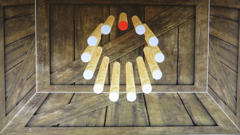
Figure 5: Fitts' law 3D task.
4.1 Participants
Twelve participants (four female) were recruited from the local university including undergraduate students, graduate students, and alumni. Ages ranged from 19 to 40 (μ = 25.8, σ = 5.1 years). Based on participants' self-reporting, three had moderate experience with 3D controllers, three had low experience, and six had no experience. All participants had normal stereo acuity as determined by testing on the 3D system. All were right-handed.
4.2 Apparatus
4.2.1 Hardware
The wearable input device consisted of the three IMUs described in Section 3. One sensor was mounted on each of the upper and lower arms. The third device was mounted on the hand, exclusively for the twist selection method (detailed in Section 3.1). Participants wore stereo 3D LCD shutter glasses (NVIDIA 3D Vision 2 Wireless Glasses) throughout the experiment. The host computer included an AMD Athlon II X4 635 CPU running at 2.90 GHz with 4.00 GB RAM, a Microsoft 64 bit Windows 7 Enterprise SP1 operating system, and an NVIDIA GTX 560 TI video card. The display monitor was a BenQ XL240T running at 120 Hz. The click selection method utilized an after-market clone of the Nintendo Wii Nunchuk with the switch connected to a digital input on one of the sensors (Figure 6). The controller was held in the dominant hand as consistent with the dwell and twist selection methods, thus avoiding a potential confound. The twist selection method required a third inertial sensor worn on the hand to detect rotation about the roll axis. No extra hardware was needed for the dwell selection method.
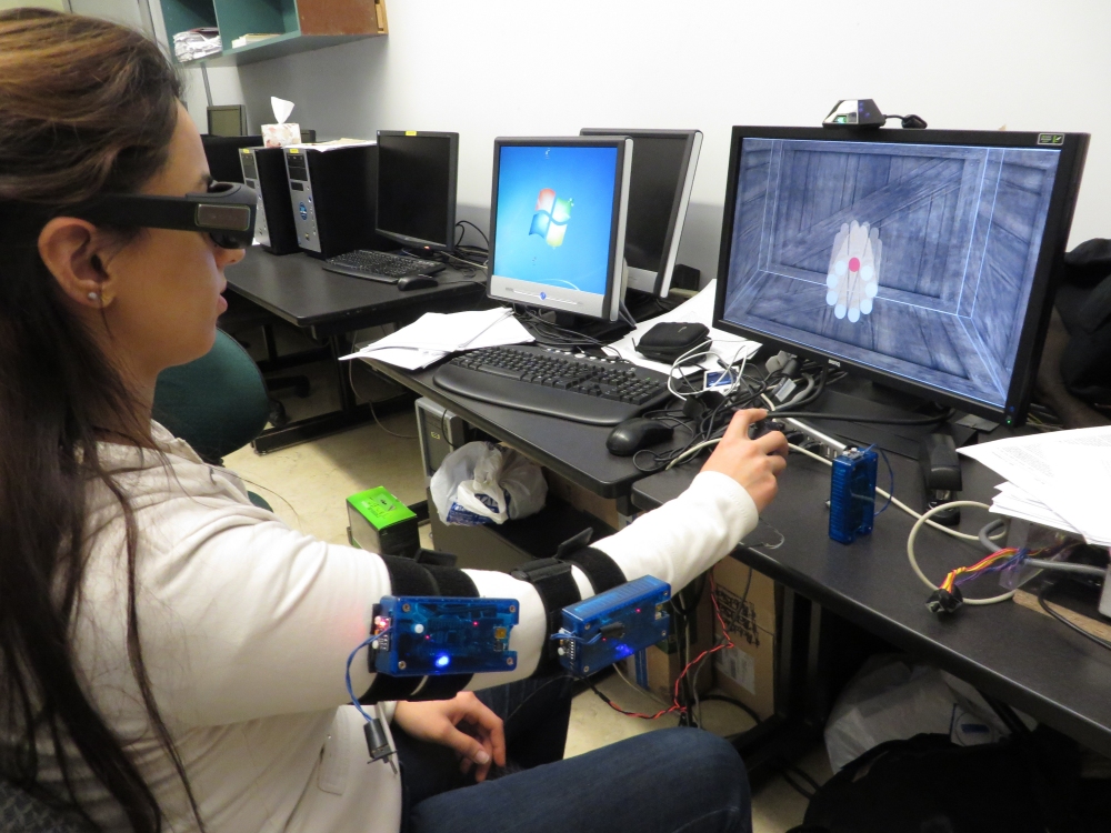
Figure 6: A participant using the click selection method.
4.2.2 Software
The scene depicted a 30 cm deep box. The width and height of the box were 51 cm and 29 cm, respectively, matching the dimensions of the LCD monitor. Target volumes were placed at three different depths: screen depth (0 cm), 5 cm "into" the screen, and 10 cm into the screen. Each target volume was placed on a support cylinder as a visual aid (Figure 5). The scene was displayed in stereo 3D, providing participants with additional depth information about the target positions. Head-tracking was not used. A three-dimensional cursor shaped like a jack was used as the selection tool.
The software automatically recorded and calculated movement time, error rate, and throughput. Both the twist and dwell selection methods were implemented in software.
4.2.3 Task and Target Parameters
The reciprocal tapping task required participants to select thirteen targets arranged in a circle. The target to select was red (see Figure 5) and turned blue upon cursor entry to provide user feedback. As the task was 3D, the targets were spheres and required 3D selection precision. The software to control the task was provided by Teather and Stuerzlinger and modified from their previous work [50].
There were three target amplitudes, A = 3.5 cm, 5.5 cm, and 7.5 cm, three target diameters, W = 0.5 cm, 1.0 cm, and 1.5 cm, and three target depths, D = 0 cm (at screen depth), -5.0 cm, and -10.0 cm (behind the screen). Thus, there were 27 A-W-D combinations. The presented IDs ranged from 2.17 bits to 4.00 bits, as calculated with Equation 2.
Each selection method was used for an entire session, with each session consisting of the 27 A-W-D combinations organized in sequences of 13 trials (individual target selections). Timing started with the first selection in each sequence. Hence each sequence consisted of 12 recorded trials. For each trial, the movement time was recorded. An error was logged if selection occurred with the cursor outside the target, except for the dwell selection method, as noted in Section 3.1.
4.3 Procedure
Upon arrival and after providing informed consent, participants were introduced to the experiment task using each of the three selection methods. For each session, participants were seated in a comfortable position away from the target surface with enough room to move their arms. Each participant was given roughly two to five minutes of practice trials with each selection method and to assess stereo acuity. They were instructed to maximize both movement speed and accuracy, emphasizing accuracy. After each session with each selection method (consisting of 324 selection trials), participants rated their level of physical comfort. At the end of the study, participants completed a questionnaire with ratings for mental effort, physical comfort, and ease of use for each selection method.
4.4 Design
The experiment used a within-subjects design with the following independent variables and levels:
| Selection Method: | Click, Dwell, Twist | |
| A: | 3.5 cm, 5.5 cm, 7.5 cm | |
| W: | 0.5 cm, 1.0 cm, 1.5 cm | |
| D: | 0 cm, -5 cm, -10 cm |
Note that target depths are relative to the screen, hence -5 cm indicates a target was 5 cm behind the screen surface. A Latin square was designed consisting of 3 selection methods and 3 target depths yielding 9 combinations. With 12 participants split up into groups of three, the 4th group repeated the sequence from the 1st group. Target size and amplitude within each session were randomly ordered (without replacement). The duration of the experiment was roughly 1.5 hours per participant. In total, each participant completed 3 selection methods × 3 amplitudes × 3 widths × 3 depths × 12 trials = 972 trials. Over twelve participants, this yielded 11,664 recorded trials.
The dependent variables were movement time (ms), error rate (% of missed targets), and throughput (bits/s).
5 RESULTS
Movement times for the three selection methods were in the 3 – 4 second range. See Figure 7. A Shapiro-Wilk test indicted that movement time was normally distributed (w = 0.987, p > .01). One-way ANOVA indicated significant differences in movement time between the selection methods (F2,11 = 3.83, p < .05). However, Bonferroni-Dunn post-hoc tests at the α = .05 level failed to detect pairwise differences. We speculate that dwell and twist may be significantly different, as their movement times were most different.

Figure 7: Movement time (ms) by selection method. Error bars show ±1 SE.
Mean error rates for the click, dwell, and twist selection methods are seen in Figure 8. Note that the error rate for dwell is always 0% since each trial ends with the cursor inside the target volume. A Shapiro-Wilk test indicated that error rate data were not distributed normally (w = 0.855, p < .01), thus we followed with a non-parametric Friedman test. Results indicate significant differences in the mean error rate by selection method (χ2 = 19.5, p < .0005, df = 2). Post hoc pairwise tests using Conover's F at the α = .05 level revealed significant differences between all three selection methods.
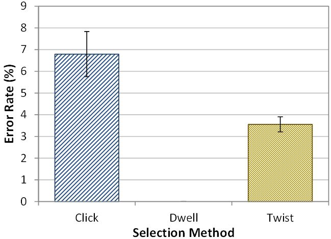
Figure 8: Error rate (%) by selection method. Error bars show ±1 SE.
Throughput was calculated as described in Section 2.4. The mean throughputs for the click, dwell, and twist selection methods were 1.12 bits/s, 1.08 bits/s, and 1.05 bits/s, respectively (Figure 9). A Shapiro-Wilk test indicated that the data were not distributed normally (w = 0.875, p < .01), so we again used a non-parametric Friedman test for analysis. The Friedman test revealed no significant differences in throughput by selection method (χ2 = 0.500, p > .05, df = 2).
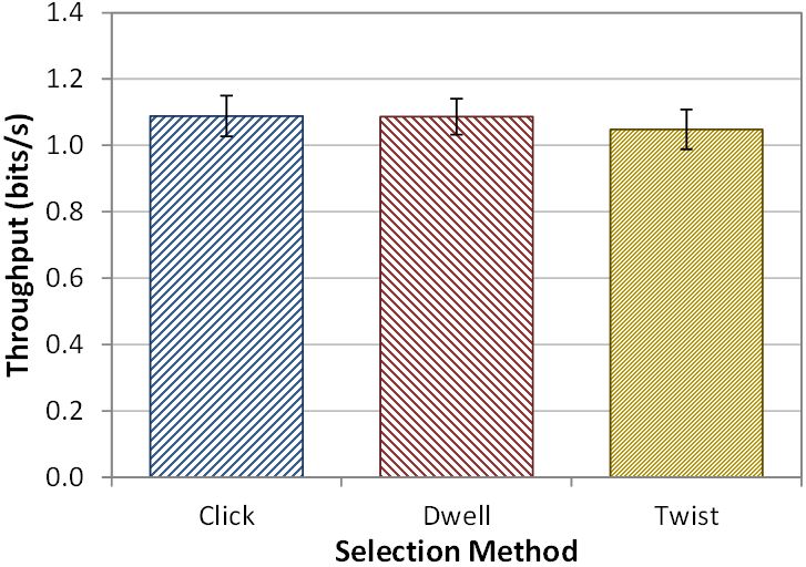
Figure 9: Throughput (bits/s) by selection method. Error bars show ±1 SE.
6 DISCUSSION
6.1 Performance Results
The grand mean for throughput was roughly 1.08 bits/s. A few previous studies have looked at similar "touch"-based 3D interaction techniques. For example, Teather and Stuerzlinger [48] report throughputs between 2.5 and 3.5 bits/s, depending on target depth, and throughput around 3.8 – 4.0 bits/s in subsequent work using a NaturalPoint OptiTrack tracker [47]. Movement times ranged from roughly 1.0 s to 2.4 s while the movement times from this experiment were roughly 3.0 s. Bruder et al. [6] report throughputs of 3 – 4 bits/s, depending on target depth, with a direct touch 3D technique implemented with a WorldViz optical tracker. Because these studies used the same experimental methodology, we conclude that our device offered substantially lower performance than these studies using optical trackers.
There were no significant differences in movement times or throughputs between selection methods. Moving the cursor between targets required the same motions consisting of a ballistic phase and a corrective phase. However, we expected some difference between the selection methods, since dwell required a 500-ms delay, twist used a 100-ms sticky interval, and click required no timing interval. We note that dwell had the highest overall movement time, as expected. However, we can only speculate that this was significantly higher than twist, since our statistical tests failed to detect significant differences. This suggests that there are other factors more significant than the dwell time. Latency is a candidate, discussed in detail below.
Error rates were significantly different between all three selection methods. This is unsurprising as dwell always has a 0% error rate. We suspect the better accuracy with the twist method is due to the aforementioned "sticky" cursor feature. It is possible that a sticky cursor feature could also benefit the click method. However, the influence of the Heisenberg effect on click was deemed minimal, since only one finger moves to activate the click button. In contrast, movement of the whole hand as well as the forearm is required with the twist method.
It is surprising that despite substantial differences in error rate, and slight (potentially significant) differences in movement time, throughput was roughly the same across the three selection methods. Given the low error rate of twist, and the fact that it had the lowest movement time, one would expect throughput to be highest with twist. As seen in Equation 3, throughput is calculated using the standard deviation in the selection coordinates about the targets. Since missing was impossible with dwell, this distribution was small, and the average distance from target centre was 0.38 cm (well below the average target size of 0.50 cm). While such accurate selections would yield a correspondingly higher throughput (see Equation 3), the higher movement time also contributed to reducing throughput for dwell. However, the twist selection method did not offer such accurate selections due to the "sticky" function. We note here the difference between error rate (percentage of trials that missed) and error magnitude (i.e., the range of the selections relative to target centre). While the sticky function likely improved the twist error rate relative to click, it also ensured that selection coordinates were only possible on or near the surface of the target volumes since further motion is suspended upon immediate entry. Hence error magnitude (which directly influences throughput) was higher with twist than the other selection methods. With twist, selection coordinates were, on average, 0.49 cm from the target centre – on average, on or near the surface of the targets. We believe that this higher error magnitude is what yielded proportionally worse throughput scores with twist.
6.2 Fatigue
In-air unsupported pointing is a physically demanding task. Over time, it was observed that participants experienced increasing levels of fatigue and both error rates and movement times increased. Each block of trials consisted of 351 target selections. Prior to running the study, pilot testing revealed that very few participants could consecutively perform all 27 sequences (even with only 9 trials per sequence). Fewer achieved acceptable error rates which approached 50% in some sequences. The experiment parameters were changed considering the excessive fatigue participants experienced in the pilot study.
For the experiment, we employed CD gain as described in Section 3. This provided a reasonable balance between fatigue reduction and error. Additionally, prior to clicking the first target in each circle (which started the timing for each sequence), participants were encouraged to rest for ten to twenty seconds. This rest greatly mitigated fatigue and, with this, all participants could complete the study with minimal errors. Incidentally, during this rest period the drift of the device was also zeroed out, as described in Section 3.
6.3 3D vs 2D Movement
For cursor movement, there was a direct mapping of real world coordinates to the virtual screen position. Cursor or pointer acceleration functions, such as those designed to maximize precision, were not implemented. It was observed that participants were initially not able to easily reach the targets. Although the stereo depth cues provide some notion of three dimensions, many participants moved their arms initially while not understanding that the trajectory of the cursor in three dimensions follows an arc rather than a straight line. This issue might be eliminated by using direct touch, that is, coupling the cursor position to the actual hand position. As noted earlier, this was not possible with our setup, but could be employed using, for example, a head-mounted display with targets presented in the same spatial frame of reference as the user (rather than "behind" the screen surface).
6.4 Physical Setup
There were several issues in the experimental setup that warrant discussion. As noted previously, the CD gain settings were chosen to maximize comfort and performance. However, another factor is the physical location of the work area displayed in real world coordinates. Because the wearable input method uses a virtual hand (depth cursor) metaphor, the onscreen cursor mimics the motion and position of the user's real hand. Thus, the participants in the study found that their real hand visually occluded the onscreen targets in certain circumstances. We note again that using a head-mounted display would prevent this (necessitating rendering of a virtual 3D hand, or similar).
One possible solution was to offset the location of the work area either upwards or downwards, but this proved problematic. If the arm motions were lower, the user must compensate by moving their arms higher, thus causing more fatigue and discomfort. A higher offset was problematic as users compensated by moving their arms lower. Because users were seated, their arms would contact their legs in order to reach lower targets. Thus, proper gain settings and height offsets are required to avoid these problems. As previously discussed, increasing CD gain allows smaller arm movements to produce larger cursor movements, but accuracy and error rates suffer. This is a known problem which is potentially obviated through non-linear transfer functions like the pointer acceleration used in desktop operating systems, such as Microsoft Windows. However, a desktop context is inappropriate for a wearable input method. A large high resolution display or a CAVE where users stand up may be a more suitable application. Alternatively, such issues would not arise with a head-mounted display.
6.5 Latency
Latency was visually noticeable but not measured. We estimate it to be on the order of 200 ms. Studies measuring human neural response through magneto-encephalography have found that the time between the perception of visual stimulus to manual reaction is on the order of 150 to 200 ms [1, 51]. Response time is a factor in the correction phase of movement. The participant requires visual feedback to correct their arm position when placing the 3D cursor.
Examining the overall system for possible sources of latency is complicated. Starting from the sensors, the sampling rate of each accelerometer/gyro unit was 25 Hz yielding one sample every 40 ms. A lag of 40 ms is significant as determined by MacKenzie and Ware [27]. Higher sampling rates are possible, up to 100 Hz, but the FIFO buffer in combination with the Arduino FIO I2C communications bus was unstable. Communications with the sensors to the host computer were implemented through Digikey Xbee radios running at 57600 bps. Each packet containing quaternion data sent from the Arduino is approximately 150 bits for a data transfer rate of approximately 384 packets per second. Thus, the bottleneck in the sensor and communication system to the host computer is the 40 ms sampling rate. Increasing the wireless data rate would be futile. Each sensor communicates on its own wireless channel with the host computer to eliminate the risk of packet collisions and resends.
The next step in the chain is the Java-based programming environment. The code imports the raw quaternion data from the sensors and performs calculations to determine the Cartesian coordinates of the depth cursor location in virtual space. The software must also detect the click, dwell, and twist selection events. The RxTx package for Java serial communications specifies a polling interval for serial/USB ports of 20 ms. This is less than half the sampling rate of the accelerometer/gyro sensors and is acceptable in the overall system. Should the sampling rate increase, the polling interval must shorten to accommodate the increased packet rate. The code does not use interrupts, but polls the serial ports in an infinite loop. It is unknown whether the host computer running at 2.9 GHz is able to generate and output data fast enough to keep pace with the packets coming from each sensor at 25 Hz. The code also draws a wire frame representation of the user's arm continuously in order to visually verify that calibration of each sensor is maintained throughout each block of trials. Performance of the Java Virtual Machine for real time applications is problematic as well.
During the experiment, two monitors are used with the host computer. One of the monitors shows the wire frame motion of the sensors, while the 3D monitor depicts the fish tank VR working environment. This may be the source of a system bottleneck.
The software outputs three-dimensional position information in the form of a text file which is then read by a modified version of the fish tank VR software provided by Teather and Stuerzlinger [48]. This software generates the log data for the user study. Transfer of data through a text file is another likely source of substantial system delay.
Ultimately, with an improved implementation that minimizes latency, we expect the performance measures of the device to increase considerably. Based on MacKenzie and Ware [27] or Teather et al. [46], we anticipate that throughput would roughly double if latency were reduced to 40 ms or less (from the current ~200 ms). While this would be more competitive with other results [6, 48], it is still rather low. Hence, future work will focus on reducing latency and further optimizing the design of the input device to improve performance.
7 CONCLUSIONS
The wearable input method achieved a low throughput of roughly 1.08 bits/s as compared to the NaturalPoint OptiTrack system's 3.5 bits/s, and half the error rate at 6.82% for the baseline click selection method. The twist selection method had an error rate of 3.59% while the dwell method disallowed errors, and surprisingly, did not adversely affect movement time significantly.
Unsupported pointing with a user's arm is physically demanding. Using a higher CD gain might offset some fatigue, as it shortens the required arm motions. However, higher CD gain levels also increase error rates, particularly for small targets. Hence an interesting prospect for future work is to investigate dynamic CD gain levels, i.e., "pointer acceleration" to leverage the benefits of both high and low CD gain.
Designing an input system in general must consider sources of latency. In the case of a wearable inertial sensor system, the refresh rate of the sensors should be examined and the system must be kept in constant calibration due to potential gyro drift problems as well as physical slippage when worn on the body. We suspect that, with refinement, an improved gyro-based input device might offer more competitive performance levels by considering the optimizations described above.
REFERENCES
[1] Amano, K, Goda, N, Nishida, S, Ejima, Y, Takeda, T, and Ohtany, Y.
Estimation of the timing of human visual perception from
magnetoencephalography. The Journal of Neuroscience, 26(15) (2006),
Society for Neuroscience, pp. 3981–3991.
[2] Argelaguet, F, and Andujar, C. A survey of 3D object selection techniques
for virtual environments. Computers & Graphics 37(3) (2013), Elsevier,
pp. 121-136.
[3] Bachmann, E R, Xun, X, and McGhee, R B. Sourceless tracking of human
posture using small inertial/magnetic sensors. In Proceedings of the IEEE
International Symposium on Computational Intelligence in Robotics and
Automation (Kobe, JP, July16-20, 2003), IEEE, pp. 822-829.
[4] Bérard, F, Ip, J, Benovoy, M, El-Shimy, D, Blum, J R, and
Cooperstock, J R. Did "Minority Report" get it wrong? Superiority of the
mouse over 3D input devices in a 3D placement task. In IFIP Conference on
Human-Computer Interaction (Uppsala, Sweden, Aug 24-28, 2009), Springer,
pp. 400-414.
[5] Bowman, C, Wingrave, C, Campbell, J, and Ly, V. Using pinch gloves
for both natural and abstract interaction techniques in virtual
environments. In Proceedings of HCI International (New Orleans, LA, Aug
5-10, 2001), Lawrence Erlbaum, pp. 629-633.
[6] Bruder, G, Steinicke, F, and Stuerzlinger, W. To touch or not to
touch?: Comparing 2D touch and 3D mid-air interaction on stereoscopic
tabletop surfaces. In Proceedings of the ACM Symposium on Spatial User
Interaction - SUI 2013, (Los Angeles, CA, July 20-21, 2013), ACM, pp.
9-16.
[7] Burstyn, J, Strohmeier, P, and Vertegaal, R. DisplaySkin: Exploring
pose-aware displays on a flexible electrophoretic wristband. In
Proceedings of the International Conference on Tangible, Embedded, and
Embodied Interaction - TEI 2015, (Stanford University, CA, Jan 15-19,
2015), ACM, pp. 165-172.
[8] Calvo, A, Burnett, G, Finomore, V, and Perugini, S. The design,
implementation, and evaluation of a pointing device for a wearable
computer. In Proceedings of the Human Factors and Ergonomics Society
Annual Meeting (Boston MA, Oct 22-26, 2012), SAGE, pp. 521-525.
[9] Calvo, A and Perugini, S. Pointing devices for wearable computers.
Advances in Human-Computer Interaction (2014), Hindawi.
[10] Cha, Y, and Myung, R. Fitts' law for 3D pointing tasks using 3D
target arrangements. International Journal of Industrial Ergonomics 43(4)
(2013), Elsevier, pp. 350-355.
[11] Colley, A, Häkkilä, J, Schöning, J, Daiber, F, Steinicke, F, and
Krüger, A. Touch the 3rd dimension! Understanding stereoscopic 3D
touchscreen interaction. In Australian Computer-Human Interaction
Conference (Adelaide, AU, Nov 25-29, 2013), Springer, pp. 47-67.
[12] Fitts, P M. The information capacity of the human motor system in
controlling the amplitude of movement. Journal of Experimental
Psychology, 47, 6 (1954), US: American Psychological Association, pp.
381-391.
[13] Hand, C. A survey of 3D interaction techniques. Computer graphics
forum, 16, 5 (1997), Wiley-Blackwell, pp. 269-281.
[14] Hinapie-Ramos, J D, Ozacar, K, Irani, P P, and Kitamura, Y.
GyroWand: IMU-based raycasting for augmented reality head-mounted
displays. In Proceedings of the ACM Symposium on Spatial User Interaction
- SUI 2015, (Los Angeles, CA, Aug 8-9, 2015), ACM, pp. 89-98.
[15] ISO. Ergonomic Requirements for Office Work with Visual Display
Terminals, Nonkeyboard Input Device Requirements, Draft 6. International
Standard, International Organization for Standardization. ISO, 1998.
[16] Jain, M, Cockburn, A, and Madhvanath, S. Comparison of
Phone-based distal pointing techniques for point-select tasks. In IFIP
Conference on Human-Computer Interaction (Cape Town, South Africa, Sept
2-6, 2013), Springer, pp. 714-721.
[17] Jankowski, J and Hachet, M. A survey of interaction techniques
for interactive 3D environments. Eurographics 2013 State of the Art
Reports (Girona, Spain, May 6-10, 2013), Eurographics Association, pp.
65–93.
[18] Jung, P, Oh, S, Lim, G, and Kong, K. A mobile motion capture system based
on inertial sensors and smart shoes. Journal of Dynamic Systems,
Measurement, and Control, 136, 1 (2013), ASME, pp. 692-697.
[19] Kharlamov, D, Woodard, B, Tahai, L, and Pietroszek, K.
TickTockRay: smartwatch-based 3D pointing for smartphone-based virtual
reality. In Proceedings of the ACM Conference on Virtual Reality Software
and Technology - VRST 2016, (Munich, Germany, Nov 2-4, 2016), ACM, pp.
363-364.
[20] Lazewatsky, D A, Bowie, C, Curran, W, LaFortune, J, Narin, B,
Nguyen, D, and Smart, W E. Wearable computing to enable robot
microinteractions. In Proceedings of the IEEE International Symposium on
Robot and Human Interactive Communication, (Edinburgh, UK, Aug 25-29,
2014), IEEE, pp. 141-146.
[21] Liu, L, Van Liere, R, Nieuwenhuize, C, and Martens, J B.
Comparing aimed movements in the real world and in virtual reality. In
Proceedings of the IEEE Virtual Reality Conference - VR 2009, (Lafayette,
LA, Mar 14-18, 2009), IEEE, pp. 219-222.
[22] Lubos, P, Bruder, G, and Steinicke, F. Analysis of direct
selection in head-mounted display environments. In Proceedings of the
IEEE Symposium on 3D User Interfaces - 3DUI 2014, (Minneapolis, MN, Mar
29-30, 2014), IEEE, pp. 11-18.
[23] MacKenzie, I S. Fitts' law as a research and design tool in
human-computer interaction. Human-computer interaction, 7, 1 (1992),
Taylor & Francis Online, pp. 91-139.
[24] MacKenzie, I S. Fitts' throughput and the remarkable case of
touch-based target selection. In Proceedings of the International
Conference on Human-Computer Interaction – HCII 2015 (Los Angeles, CA,
Aug 2-7, 2015), Springer, pp. 238-249.
[25] MacKenzie, I S and Buxton, W. Extending Fitts' law to two
dimensional tasks. In Proceedings of the ACM Conference on Human Factors
in Computing Systems - CHI '92, (Monterey, CA, June 3-7, 1992), ACM, pp.
219-226.
[26] MacKenzie, I S and Isokoski, P. Fitts' throughput and the
speed-accuracy tradeoff. In Proceedings of the ACM Conference on Human
Factors in Computing Systems – CHI 2008 (Florence, IT, May 5-10, 2008),
ACM, pp. 1633-1636.
[27] MacKenzie, I S, and Ware, C. Lag as a determinant of human
performance in interactive systems. In Proceedings of the ACM Conference
on Human Factors in Computing Systems - CHI '93, (Amsterdam, NL, April
24-29, 1993), ACM, pp. 488-493.
[28] Müller-Tomfelde, C. Dwell-based pointing in applications of human
computer interaction. In Human-Computer Interaction–INTERACT 2007 (Rio de
Janeiro, BR, Sept 12-14, 2007), Springer, pp. 560-573.
[29] Murata, A. Extending effective target width in Fitts' Law to two
dimensional pointing task. International Journal of Human Computer
Interaction, 11 (1999), Taylor & Francis Online, pp. 137-152.
[30] Murata, A and Iwase, H. Extending Fitts' law to a
three-dimensional pointing task. Human Movement Science, 20, 6 (2001),
Elsevier, pp. 791-805.
[31] Oakley, I, Sunwoo, J, and Cho, I Y. Pointing with fingers, hands
and arms for wearable computing. Extended Abstracts on Human Factors in
Computing Systems, CHI-EA 2008 (Florence, IT, April 5-10, 2008), ACM, pp.
3255-3260.
[32] Ortega, F R, Abyarjoo, F, Barreto, A, Rishe, N, and Adjouadi, M.
Interaction Design for 3D User Interfaces: The World of Modern Input
Devices for Research, Applications, and Game Development. A K Peters/CRC
Publishing, 2016.
[33] Pagano, R R. Understanding statistics in the behavioural
sciences. Wadsworth Publishing, 2006.
[34] Pavlovych, A and Stuerzlinger, W. The tradeoff between spatial
jitter and latency in pointing tasks. In Proceedings of the ACM Symposium
on Engineering Interactive Computing Systems - EICS 2009, (Pittsburgh,
PA, July 15-17, 2009), ACM, pp. 187-196.
[35] Pietroszek, K. 3D Pointing with Everyday Devices: Speed,
Occlusion, Fatigue. University of Waterloo, Waterloo, 2015.
[36] Pietroszek, K, Kuzminykh, A, Wallace, J R, and Lank, E.
Smartcasting: a discount 3D interaction technique for public displays. In
Proceedings of the 26th Australian Computer-Human Interaction Conference
on Designing Futures: the Future of Design (Sidney, AU, Dec 2-5, 2014),
ACM, pp. 119-128.
[37] Prayudi, I, and Kim, D. Design and implementation of imu-based
human arm motion capture system. In IEEE International Conference on
Mechatronics and Automation (Chengdu, CN, Aug 5-8, 2012), IEEE, pp.
670-675.
[38] Raya, R, Roa, J O, Rocon, E, Ceres, R, and Pons, J L. Wearable
inertial mouse for children with physical and cognitive impairments.
Sensors and Actuators A: Physical, 162, 2 (2010), Elsevier, pp. 248-259.
[39] Rico, J, Crossan, A, and Brewster, S. Gesture-based interfaces:
Practical applications of gestures in real world mobile settings. Whole
Body Interaction (2011), Springer, pp.173-186.
[40] Skogstad, S A, Nymoen, K, and Høvin, M E. Comparing inertial and
optical mocap technologies for synthesis control. In Proceedings of the
Sound and Music Computing Conference (Padova, IT, July 6-9, 2011),
Creative Commons, pp. 421-426.
[41] Solberg, R T and Jensenius, A R. Optical or Inertial? Evaluation
of two motion capture systems for studies of dancing to electronic dance
music. In Proceedings of the SMC Conferences (Hamburg, DE, Aug 23-Sept 3,
2016), Creative Commons, pp. 469-474.
[42] Soukoreff, R W and MacKenzie, I S. Towards a standard for
pointing device evaluation, perspectives on 27 years of Fitts' law
research in HCI. International Journal of Human-Computer Studies, 61, 6
(2004), Elsevier, pp.751-789.
[43] Teather, R J. Evaluating 3D pointing techniques. York University,
Toronto, 2013.
[44] Teather, R J, Allison, R S, and Stuerzlinger, W. Evaluating
visual/motor co-location in fish-tank virtual reality. In IEEE Toronto
International Conference Human Factors and Ergonomic Symposium (Toronto,
ON, Sept 26-27, 2009), IEEE, pp. 624-629.
[45] Teather, R J and MacKenzie, I S. Position vs. velocity control
for tilt-based interaction. In Proceedings of Graphics Interface 2014
(Montreal, QC, May 7-9, 2014), Canadian Information Processing Society,
pp. 51-58.
[46] Teather, R J, Pavlovych, A, Stuerzlinger, W, and MacKenzie, I S.
Effects of tracking technology, latency, and spatial jitter on object
movement. In 3D User Interfaces - 3DUI 2009 (Lafayette, LA, Mar 14-15,
2009), IEEE, pp. 43-50.
[47] Teather, R J and Stuerzlinger, W. Pointing at 3d target
projections with one-eyed and stereo cursors. In Proceedings of the
SIGCHI Conference on Human Factors in Computing Systems (Toronto, ON,
April 26-May 1, 2014), ACM, pp. 159-168.
[48] Teather, R J and Stuerzlinger, W. Pointing at 3D targets in a
stereo head-tracked virtual environment. In IEEE Symposium on 3D User
Interfaces (Singapore, Mar 19-20, 2011), IEEE, pp. 87-94.
[49] Teather, R J and Stuerzlinger, W. Target pointing in 3D user
interfaces. In Proceedings of the Graphics Interface Poster Session (GI
2010), (Ottawa, ON, May 31-June 2, 2010), pp. 20-21.
[50] Teather, R J and Stuerzlinger, W. Visual aids in 3D point
selection experiments. In Proceedings of the 2nd ACM Symposium on Spatial
User Interaction (Honolulu, HI, Oct 4-5, 2014), ACM, pp. 127-136.
[51] Thompson, P D, Colebatch, J G, Brown, P, Rothwell, J C, Day, B L,
Obeso, J A, and Marsden, C D. Voluntary stimulus-sensitive jerks and
jumps mimicking myoclonus or pathological startle syndromes. Movement
Disorders, 7, 3 (1992), Wiley, pp. 257-262.
[52] Ware, C and Balakrishnan, R. Reaching for objects in VR displays:
Lag and frame rate. ACM Transactions on Computer-Human Interaction, 1, 4
(1994), ACM, pp. 331–356.
[53] Yun, X and Bachmann, E R. Design, implementation, and experimental
results of a quaternion-based Kalman filter for human body motion
tracking. IEEE Transactions on Robotics 22(6) (2006), IEEE, pp.
1216-1227.
[54] Yun, X, Bachmann, E R, Moore, H, and Calusdian, J. Self-contained
position tracking of human movement using small inertial/magnetic sensor
modules. In Proceedings of the IEEE Conference on Robotics and Automation
(Rome, IT, April 10-14, 2007), IEEE, pp. 2526-2533.
Footnotes:
1. http://sixense.com/razerhydra
2. http://polhemus.com/motion-tracking/all-trackers/patriot/
3. http://www.ndigital.com/msci/products/aurora/
4. http://optitrack.com/
5. https://www.vicon.com/
6. http://www.3dconnexion.com/products/spacemouse.html
7. http://support.logitech.com/en_za/product/mx-air-rechargeable-cordless-air-mouse
8. http://www.geomagic.com/en/products/phantom-omni/overview
9. http://www.novint.com/index.pp/novintfalcon