3. COMPUTER INPUT
As bit-mapped graphic displays accompanied by sophisticated input transducers proliferate, rich techniques for human-computer interaction will emerge. It remains to be seen whether editing an electronic document can be as direct as marking-up a paper document using proofreader symbols – with changes appearing immediately. Nevertheless, user input will develop to be more direct, more intuitive.
Present-day mouse-driven interfaces already employ sophisticated yet natural techniques for user input. "Pointing", "dragging", "inking" – these tasks were popularized by the Apple Macintosh using the mouse and a graphical user interface. Today, they form the core repertoire of interaction techniques for every Mac user. Similar window and icon-based environments are emerging as the preferred choice on many MS-DOS and Unix-based systems. In this section, we shift our emphasis from the theoretical issues underlying Fitts' law to computer input. Our focus is on input devices, interactive tasks, and the underlying factors that determine increments or decrements in performance. We are, of course, interested in laying the groundwork for the application of Fitts' law as a performance model for different devices and tasks so that performance differences can be empirically determined and predictions made.
3.1 Device Differences
In Fitts' original research, very similar performance measures were found using a 1 oz stylus and a 1 lb stylus (see Table 2). The differing mass, however, represents a parametric change for the same device – a "within-device" difference, we might say. Had devices with different means of effecting motion been used, the same observation may not have followed. The possibility of "between-device" performance differences has motivated a substantial body of Fitts' law research in human factors, with the goal of establishing performance tradeoffs for input devices to machinery or vehicles. What, then, are the properties that distinguish input devices and cause performance tradeoffs? These are identified in the following paragraphs.
3.1.1 Rotary vs. Linear Motion
Although a cursor on a CRT display undergoes simple planar motion, different possibilities exist for effecting this motion via an input device. Two possibilities are rotary vs. linear motion. A simple example of a rotary system is a station knob on an FM tuner. Rotary motion of the knob is mapped into linear motion of the station slider.
Considering two common input devices, such as a mouse and a trackball, we find distinct differences between the two. A mouse undergoes linear motion on a desktop whereas a trackball undergoes rotary motion. Rotary motion is also present in displacement joysticks which swivel about their base to effect motion of the tracking symbol. These kinematic differences may be a source of performance differences.
3.1.2 Displacement vs. Force Sensing
Some devices move while others are force sensing and undergo negligible motion. Joysticks of the latter type are called "isometric" (e.g., see Card et al., 1978; Kantowitz & Elvers, 1978; Sherr, 1988) and translate the direction of the applied force into cursor motion. Touch screens and tablets appear to have both characteristics, responding to the 2-D displacement of the finger or stylus and the applied pressure, though few respond to graded differences in pressures.
3.1.3 Absolute vs. Relative Positioning
Some devices (e.g., a tablet) have a detached or out-of-range state while others do not (e.g., a trackball). When "re-connecting", cursor positioning may continue relative to the current position or at a new absolute coordinate. A requirement of absolute positioning is the ability to sense the transitions between the detached and connected states. Although a mouse can be lifted from the desktop, this cannot be sensed; thus, positioning is strictly relative.
3.1.4 Dimensions Sensed
Devices may operate in one, two, or three spatial dimensions. Potentiometers and sliders are obvious examples of 1-D devices, but others exist (see Buxton, 1983). Most computer input devices are 2-D, but a few 3-D devices are starting to emerge, such as the "data glove" (Zimmerman et al., 1987) or 3-D mouse (Ware & Baxter, 1989).
3.1.5 Control-Display Gain
Control-display (C-D) gain is a measure of how much displacement or force a controller, such as a mouse or joystick, must undergo to effect one unit of movement in a displayed tracking symbol, such as a cursor or cross-hair. Many researchers have attempted to optimize performance parameters such as movement speed or accuracy by varying control-display gain. Usually a simple linear relationship is in effect, but, recently, the notion of non-linear control-display functions has emerged as a potential way to optimized performance.
Kantowitz and Elvers (1988) found an interaction effect with a higher C-D gain improving performance with a velocity control joystick but not with a position control joystick. The majority of studies, however, found that significant performance benefits cannot be achieved by adjusting C-D gain (Arnault & Greenstein, 1988; Buck, 1980; Gibbs, 1962; Jackson, 1984; Langolf et al., 1976), even through various non-linear C-D relationships (Jellinek & Card, 1990; Olson, 1986).
3.1.6 Spatial Transformation
Fitts' stylus is a device which is manipulated directly with very little spatial transformation. The task is to strike a metal plate and this is precisely and directly what the stylus does. Baseball bats and violin bows have similar properties.
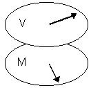
Most computer input devices are manipulated in a spatially transformed plane from the cursor or tracking symbol that they control. The transformation is described by the type and extent of mapping from the visual space to the motor space, or "V-M mapping". The mapping may be linear (also called congruent) or rotary (see Figure 8). Although extensive research has not been conducted, Cunningham (1989) found performance decrements under rotary V-M mappings of 90° to 135° but no decrement for a 180° transformation. A 180° transformation is used in some studies (e.g., Jagacinski, Repperger, Moran, Ward, & Glass, 1980) to turn the stimulus-response compatibility "inside-out", simulating the effect of centering a viewing window over a stationary target.
(a) (b)
Figure 8. Spatial transformation between visual space and motor space. (a) Congruence (b) Clockwise 90° rotation (from Cunningham, 1989)
Although touch screens (and various forms of on-screen styli) are the only input devices for which there is no inherent spatial transformation, implementations usually introduce a slight linear displacement to keep the finger from covering the tracking symbol (Potter, Welden, & Shneiderman, 1988).
3.1.7 Interactions Between Muscle Groups and Limb Groups
When devices contain switches or buttons for evoking actions, interactions between muscle groups and limb groups may be introduced. For example, the mouse is manipulated by arm motion (primarily the forearm or wrist) whereas the trackball is manipulated by finger or palm motion. The button is actuated by a finger on the mouse (usually the index finger) and by a finger or thumb on the trackball. Since mouse movement is primarily through the wrist or forearm, the use of a finger for select operations introduces less muscle and limb interaction than the same operation on a trackball where fingers are busy moving, stopping, and stabilizing the ball and controlling the select button.
The device differences cited above are considerable. It is not surprising, then, that researchers are evaluating the benefits or pitfalls of different devices in combination with different interaction styles. Notable taxonomies include Buxton's (1983) classification by physical property sensed and Foley, Wallace, and Chan's (1984) schematic relationship between graphic applications and input devices.
Research Question: Do different devices display different speed-accuracy characteristics as modeled by Fitts' law? (H6, H7, & H8)
3.2 Task Differences
Our investigation of the properties of input devices will proceed using Buxton's three-state model for input devices (Buxton, 1990; Buxton, Hill, & Rowley, 1985). The model presupposes that input devices act in one of three states: S0 (e.g., out-of-range), S1 (e.g., tracking), and S2 (e.g., dragging). The power of the model is its ability to match the features of input transducers with a variety of interaction techniques.
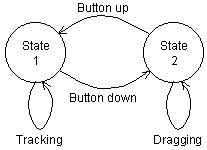
A typical transaction in the model, shown in Figure 9, is moving an icon to the trash can on a Macintosh-style interface. The cursor is moved to the icon (S1, tracking) and then the icon is moved to the trash can (S2, dragging). The mouse button provides the means for the initial S1-S2 transition (button down) and the final S2-S1 transition (button up). The button is held down during State 2 motion. Although "dragging" is adopted as a generic term for State 2 motion, inking, tracing, rubber banding, selecting from a pull-down menu, and gestural input include similar actions.
Figure 9. State 1-2 transactions using a mouse (after Buxton, 1990)
A touch tablet provides a good illustration of a State 0 transaction (see Figure 10). While the finger is touching the tablet, the cursor follows the finger (S1, tracking). Lifting the finger causes a S1-S0 transition to the out-of-range state. Initially it appears that a similar state change occurs with a mouse by lifting it from the desktop, but there's a difference. Lifting one's finger from a touch screen is sensed and suitable transactions can be devised; no action is sensed and no transaction can be implemented for lifting a mouse. Comparing Figure 9 and Figure 10, each device has a state the other cannot reach.
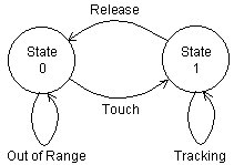
Figure 10. State 0-1 transactions with a touch tablet (after Buxton, 1990)
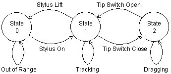
A graphics tablet with stylus can reach all three states (see Figure 11). States 0 and 1 are achieved as with the touch screen. S1-S2 state changes occur through a change in the applied pressure or through a switch built in to the stylus and activated by the index finger.
Figure 11. State 0-1-2 transactions with a graphics tablet with stylus (after Buxton, 1990)
Although the three-state model fits a rich assortment of devices and interaction techniques, its simplicity breaks down in some instances. Several brief examples are offered. Mice with more than one button, for example, are modeled with multiple State 2s (drag original, drag copy, etc.). Single-button mice can reach these same extra states through double-clicking or mode selection.
The positioning scheme on tablets, touch screens, and touch tablets may be relative or absolute. On relative positioning devices, the tracking symbol does not move when re-entering State 1 at a different location, whereas on absolute positioning devices the tracking symbol repositions itself when the input device (finger or stylus) re-enters State 1 at a different location. As well, some tablets sense the pressure applied to several bits of resolution. Perhaps State 1 and State 2 transactions are but two instances in a continuum.
Touch screens can "fake" State 2 transactions. If the cursor, while undergoing State 1 motion, enters a region which is a candidate for State 2 transactions (e.g., an icon), then a brief up-down motion of the finger maps subsequent motion into State 2 (e.g., the icon is "dragged").
To summarize, it is evident that State 1 and State 2 correspond to two different tasks. The most common mappings are pointing for State 1 and dragging for State 2. Fitts' law has been applied to movement tasks for State 1 transactions but not for State 2 transactions.
Research Question: Can different user input tasks, such as "dragging", be modeled according to Fitts' law, and, if so, how do the performance measures differ from conventional tasks following the Fitts' paradigm? (H6, H7, H8, & H9)