Spacecraft SystemsSpacecraft designs can be categorised according to their stabilisation method as either spin stabilised or inertially stabilised. Spin stabilised spacecraft utilise the increased moment of inertia of a spinning body to aid stabilisation. Less common today than in the designs of the 1970s and ‘80s, spin stabilised spacecraft include some geostationary weather satellites and a class of large communications satellites (the Hughes 600 series)., The design is losing favour as it is often reliant on a mechanically de-spun platform on which earth-pointing antennae and instruments are mounted—failure of which causes the total loss of the spacecraft. Inertially stabilised spacecraft are controlled similarly in all axes to hold a fixed rotational orientation in space. Increasingly the most common stabilisation method for spacecraft of 500 kg or more, inertially stabilised spacecraft provide a stable platform from which to make sensitive measurements. The spacecraft may still be spun-up for particular mission phases (such as release from the launcher or orbit injection burns), but for the operational phases of the mission, they are de-spun and acquire an inertial lock. The stability performance of the spacecraft is dependent on the type of control system and the sensors and actuators employed. Most fully stabilised spacecraft are controlled using heavy spinning gyroscopes or reaction wheels (discussed further in the attitude determination section). This description will focus on this latter type of spacecraft as they represent the more common and most technologically advanced. The design and construction of all but the smallest spacecraft is invariably broken down by the functional tasks that must be performed. A system level division is followed, both to simplify construction of an extremely complex device, and to allow a multi-national participation in the design and manufacturing task, with different companies or consortia undertaking responsibility for different systems. The body of the spacecraft, or bus, is considered distinct from the experiments or instruments that it carries, termed the payload. It is also known as the service module, as it provides services such as power, communications and a stable observation platform to the payload. The following sections discuss the tasks that the spacecraft bus performs. StructureThe structure of the spacecraft must support instruments and propellant tanks and accommodate other spacecraft systems over the life-cycle of the spacecraft. It must be strong enough to survive the high gravity, wide-band vibration of launch, interfacing securely with the launcher, yet still be light enough to conserve spacecraft mass. Traditionally, combinations of aluminium alloy honeycomb, carbon fibre and titanium are used to produce a stiff spacecraft skeleton. Figure 1 below shows an exploded view of a typical structure.
Figure 1: A Eurostar Spacecraft Bus (Telecom 2).
PowerPower is a crucial commodity aboard spacecraft. All systems are designed to minimise power consumption, often having quiescent, standby modes activated when a particular system is not in use. Power generation is usually by large solar arrays, deployed on either side of the spacecraft soon after launch (Figure 2) and oriented to face the sun, either solely by maneuvering the spacecraft in the case of fixed arrays, or in combination with an array drive motor, rotating the arrays to maximise the sun’s incidence angle. Batteries are used to meet extra demand during intensive periods (measurement taking etc.), or if the spacecraft is eclipsed by another orbital body, and are carefully cycled to prolong life.
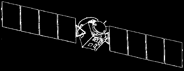
Figure 2: Rosetta (Artists Impression with Solar Arrays Extended). ThermalThe spacecraft must also maintain a reasonable thermal environment for the operation of instruments and systems. A network of heaters (usually included in each system), heat transfer pipes, and radiators dissipate surplus heat to space. Silvered Kapton heat shielding protects sun-facing equipment. The cooling system is usually passive (except for sensitive detectors). Heaters with temperature sensors control the local environment at strategic points around the spacecraft, ensuring that electronics and mechanics are maintained typically between 0Ý C and 40Ý C. Communications and Data HandlingCritical to any spacecraft, the communication and data handling system relays instrument and housekeeping data back to ground station and receives commands and instructions in return. On board the spacecraft a computer with an extended communications bus collects and distributes system information between system modules including the communications module. The particular design of the housekeeping computer employed is usually spacecraft dependent and closely linked with the design of the communications system. There is also usually a separate dedicated system passing sensor information and commands between modules of the Attitude Control system. Within Europe, the design of this system has evolved towards an industry standard known as MACS. For deep space missions, high pointing accuracy is integral to reliable communication. Ground station antennae are often high power, broadcasting thousands of watts, but still require a good fix on the spacecraft location to communicate commands successfully. Return communication is even harder to achieve. Spacecraft antennae broadcast only a few watts, often focused in a tight beam pattern to maximise receiving power. They must be carefully directed at the earth to establish communication. Wobbles in the spacecraft’s stability (as happened in the Giotto mission during approach to Halley’s comet) upset reception.
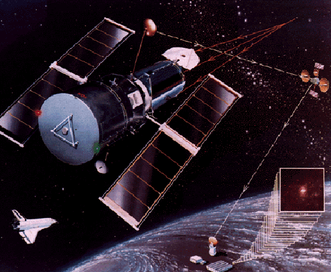
Figure 3: The Hubble Space Telescope Communicating via TDRS. Some missions utilise inter-spacecraft communication systems. Both Hubble Space Telescope and Shuttle missions return data to earth via a TDRS satellite in a higher orbit, more often in contact with particular ground stations (Figure 4), providing communications links over at least 80% of all low earth orbits. There have also been experiments with high data-rate inter-satellite communications by laser, although such a system is still experimental. With both transmitter and receiver limited in size and power, pointing accuracy must be even more precise (equivalent to a two sigma pointing accuracy of 0.03 arcsec). Propulsion SystemMost spacecraft designs include a liquid propulsion system of either mono-propellant type (usually mono-methyl hydrazine, ignited by catalyst) or bi-propellant (a fuel, usually hydrazine, and an oxidiser that combust when mixed). A network of smaller thrusters are used to apply fine adjustment impulses and are distributed about the spacecraft to allow all combinations of forces and torques to be applied to any face or about any axis. A larger single axis thruster is included to allow gross changes in spacecraft translational position. The system has two functions: first, to raise or change the spacecraft orbit; and second, to unload the spinning reaction wheels used for rotational control (discussed in the next section). The fuel is often a significant portion of the spacecraft’s overall mass (up to 60% in current designs such as the Cluster spacecraft). In a spacecraft with no significant system failures, the quantity of fuel remaining often determines the length of a spacecraft’s operational life. After all the fuel is exhausted, reaction wheels finally saturate and attitude may no longer be maintained. The storage and distribution of this fuel has significant implications for other spacecraft systems. Systems are complex and involve an extensive network of pipes and valves to ensure redundancy in the event of valve failure. The structure of the spacecraft must be capable of supporting large fuel tanks during launch. Most fuels and oxidisers are highly corrosive and explosive causing particular problems when fuelling the spacecraft prior to launch. After launch, a significant portion of the total fuel volume is often expelled to adjust the spacecraft’s translational location, placing it in its operational orbit or trajectory. Significant depletion of fuel tanks allows the fuel movement, sloshing around in the tanks—a major, unpredictable disturbance to the spacecraft. Tanks often include diaphragms or baffles to try to minimise the effect. When the fuel is burnt, and evacuated to space, the exhaust plumes must be directed away from sensitive instruments and optics to minimise interference or damage. Systems must be carefully designed to account for all these factors. Attitude Stabilisation and ControlAn attitude stabilisation system for an inertially stabilised spacecraft maintains the spacecraft’s constant orientation in space, directing communication antennae at the earth, training power-generating solar arrays on the sun, and pointing scientific cameras and instruments at objects under investigation. Determination of the current attitude is carried out by banks of sensors that sense relative orientation with respect to other bodies including the sun, earth, stars and other planets. Rate and acceleration sensors are also employed to sense motion. The attitude determination task is discussed further in the next section. Control and adjustment of attitude is by a network of actuators. Gross changes in attitude are brought about by the propulsion system—firing thrusters, burning propellant to provide impulse. Such coarse adjustments are rarely employed during normal operation because they use fuel, inject vibrations into the structure, and produce an imprecise impulse. Fine attitude control is invariably produced by reaction wheels—heavy spinning gyroscopes—grouped in packs of four to control all three axes, with a fourth spare wheel mounted skew to the others should any wheel fail. Torque impulses are produced by electric motors that increase or retard the rotation rate. Control is extremely accurate and produces low levels of unwanted vibration (due to imbalances, bearing and cage rumble and motor ripple). Recently, magnetic bearings have been developed to minimise this further. Occasionally, a reaction wheel may saturate—reach its maximum or minimum spin rate—and the spin rate of the wheel must be brought back to an acceptable level to maintain effective control. The process, called wheel off-loading, adjusts spin rate by injecting impulses from another actuator and compensating for them. Earth orbiting spacecraft often employ magnetorquers—electro-magnetic coil devices that produce an impulse in the earth’s magnetic field. Other spacecraft fire small thrusters, using valuable propellant to counter wheel saturation. Spacecraft also utilise a variety of other actuators to attain small control impulses. Solar sailing is common—adjusting the spacecraft’s profile in the sun to produce small torques or thrusts due to the action of solar radiation pressure. Ion thrusters, cold gas thrusters and other devices that conserve valuable propellant are also used. For earth orbiting satellites, approximate attitude stabilisation is often attained using static booms with masses that exploit gravity gradient effects. Next: Spacecraft Attitude Determination Systems References
|
||||||||||||||||||||||||||||
.gif)

