The primary mission payload consists of an aluminum tape tether, connected to a Spindt Array mounted on the daughter satellite. The Spindt Array is a field effect emitter and coupled with the tether forms the Electro-Dynamic Tether system. The payload also includes a stowage unit to store the tether, and a separation system used to deploy the tether in orbit. The stowage unit contains a passive braking mechanism to slow down the deployment of tether and prevent recoil.
DESCENT will deploy a 100m long aluminum tape tether. As the tether moves across the ambient plasma in LEO, an estimated +10 V bias will be induced at the anode end (mother satellite) of the tether with respect to the daughter satellite. The daughter end will be tied to the ambient plasma potential which will maintain a positive potential bias profile across the entire length of the tether.
A custom stowage unit has been designed in which the tether can be stored in a folded state. The stowage unit includes a passive braking mechanism. The stowage unit also contains a deployed tether length measurement sensor.
The tether deployment and libration dynamics have been simulated using an inclinable air-bearing turntable at York University, which can be used to emulate the deployment and libration dynamics of tethered satellites in orbit. Data planned for collection in the DESCENT mission will be used to validate these ground simulations.
The Spindt array is attached to the nadir face of the daughter cube. It will be manufactured in-house at York University. The array ejects electrons at the tip of the pins by applying a local electric field between the pin array and the grid. This will be provided via a small single cell battery with a voltage up-converter. This cell is not used to drive any current, but simply to generate sufficient potential for the electron collected by the tether back into the ambient plasma through the Spindt array.
Pre-separation, the two CubeSats will be held together by a Dyneema wire. When the ground station relays the command to deploy the tether, the wire holding the two CubeSats together will be severed using a current carrying Ni-Chrome wire. After 90m of the tether has been deployed, the passive braking mechanism described above would begin to slow down the deployment process.
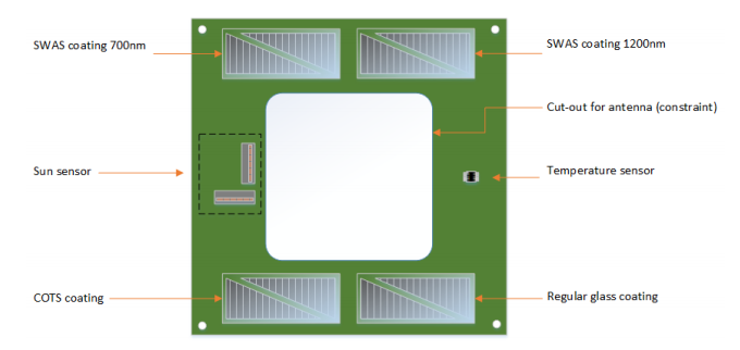
The Solar Panel Payload is comprised of a 1-U (10cm x 10cm) sized panelwith 8 individual cells, a thermometer, custom-designed digital sun sensor as well as circuitry for in-situ monitoring of solar-cell performance. Four of the 8 individual cells will deploy conventional cover glass as a protective layer, and four cells will employ SWAS-enhanced coverglass. A high number of cells is desirable to ensure accuracy in the final measurements; since the precision measurement capabilities of the current monitoring circuit are expected to be constrained by the volume, mass and power requirements of the Nano-satellite platform. A sun sensor is included in the circuit to provide a reference of the direction and intensity of the sun-vector, a crucial component for evaluating the performance of the SWAS-enhanced solar cells with respect to the incident angle of the sun. Through sufficient ground testing and by utilizing a high number of solar cells, it is expected that this payload will be able to quantify the effect of SWAS enhancement on-orbit and raise the TRL of the SWAS technology.