Stark energy shifts by matrix diagonalization
In order to test the linear Stark effect in the degenerate hydrogen atom states we perform a matrix diagonalization.
We begin with a definition of the hydrogenic bound states.
| > | restart: Digits:=14: |
| > | F:=(n,l,r)->simplify(add((-1)^i*((n+l)!)^2*r^i/(i!*(n-l-1-i)!*(2*l+1+i)!),i=0..n-l-1)); |
| > | F(1,0,r); |
![]()
| > | F(2,0,r); |
![]()
| > | F(2,1,r); |
![]()
| > | A:=(n,l)->sqrt((n-l-1)!/(2*n*((n+l)!)^3)); |
| > | Z:='Z'; |
![]()
| > | #assume(Z>0); |
| > | R:=proc(n,l,r) local k,rho; global Z; |
| > | k:=Z/n; rho:=2*k*r; |
| > | A(n,l)*rho^l*exp(-rho/2)*F(n,l,rho)*(2*k)^(3/2); end: |
| > | R(1,0,r); |
| > | int(%^2*r^2,r=0..infinity) assuming Z>0; |
![]()
| > | R(2,0,r); |
| > | int(%^2*r^2,r=0..infinity) assuming Z>0; |
![]()
| > | simplify(R(2,1,r)); |
| > | int(%^2*r^2,r=0..infinity) assuming Z>0; |
![]()
| > | plot([subs(Z=1,r*R(4,0,r)),subs(Z=1,r*R(4,1,r)),subs(Z=1,r*R(4,2,r)),subs(Z=1,r*R(4,3,r))],r=0..60,title="Hydrogen(n=4) radial orbitals"); |
![[Maple Plot]](images/StarkShift13.gif)
These radial functions are normalized. Are they orthogonal?
| > | int(expand(R(2,0,r)*R(1,0,r)*r^2),r=0..infinity) assuming Z>0; |
Maple should not have trouble with this! For some reason maple9.5 doesn't figure this one out. The problem is with the symbol Z.
| > | int(eval(expand(R(2,0,r)*R(1,0,r)),Z=1)*r^2,r=0..infinity); |
![]()
The angular parts of the wavefunctions are spherical harmonics. Let us define them:
| > | with(orthopoly); |
![]()
| > | Plm:=proc(theta,l::nonnegint,m::integer) local x,y,f; |
| > | x:=cos(theta); |
| > | if m>0 then f:=subs(y=x,diff(P(l,y),y$m)); |
| > | else f:=subs(y=x,P(l,y)); fi; |
| > | (-1)^m*sin(theta)^m*f; end: |
| > | Plm(theta,3,2); |
![]()
For the spherical harmonics we don't need the Plm's with negative argument.
| > | Y:=proc(theta,phi,l::nonnegint,m::integer) local m1; |
| > | m1:=abs(m); if m1>l then RETURN("|m} has to be <= l for Y_lm"); fi; |
| > | exp(I*m*phi)*Plm(theta,l,m1)*(-1)^m*sqrt((2*l+1)*(l-m1)!/(4*Pi*(l+m1)!)); end: |
| > | Y(theta,phi,3,0); |
| > | Y(theta,phi,3,1); |
| > | No:=(l,m)->int(int(evalc(Y(theta,phi,l,m)*conjugate(Y(theta,phi,l,m))),phi=0..2*Pi)*sin(theta),theta=0..Pi); |
| > | No(1,0); |
![]()
| > | No(1,1); |
![]()
Define an inner product for the angular degrees of freedom:
| > | IP:=(f,g)->int(int(evalc(g*conjugate(f)),phi=0..2*Pi)*sin(theta),theta=0..Pi); |
| > | IP(Y(theta,phi,1,0),Y(theta,phi,3,0)); |
![]()
The required matrix element involves as the operator the displacement z expressed as r*cos(theta)
The radial part of the matrix element is defined first. We need to set the charge:
| > | Z:=1; |
![]()
| > | RME:=(n,l,np,lp)->int(expand(r^3*R(n,l,r)*R(np,lp,r)),r=0..infinity); |
| > | evalf([RME(2,1,1,0),RME(3,1,1,0),RME(4,1,1,0),RME(5,1,1,0)]); |
![]()
Now the part where the polar and azimuthal angles theta and phi are integrated:
| > | AME:=(l,m,lp,mp)->IP(Y(theta,phi,l,m),cos(theta)*Y(theta,phi,lp,mp)); |
![]()
| > | AME(1,0,0,0),AME(2,0,0,0); |
![]()
Exercise 1:
Test the selection rules: Delta-m = 0 and Delta-l = 0, \pm 1 by trying various combinations of (l,m) with (l',m') .
Now we assemble a Hamiltonian matrix using the hydrogenic bound states. There is a danger in this approach: the bound hydrogen states are not a complete set. Results will converge, but not necessarily towards the correct eigenvalue. This problem shall be left to a mini-project at the end.
We use the fact that the problem retains axial symmetry (rotations about the z-axis), and pick a value for m :
| > | m:=0; |
![]()
There are two indeces that control the coverage of Hilbert space: a cut-off in the principal quantum number, and one in the angular momentum values to be used:
| > | n_max:=5; |
![]()
| > | l_max:=4; |
![]()
How many states are there in this sector? We can make a look-up table:
| > | i_count:=0: |
| > | for n from 1 to n_max do: |
| > | for l from 0 to n-1 do: |
| > | i_count:=i_count+1: LU[i_count]:=[n,l]: RLU[n,l]:=i_count: |
| > | od: od: N:=i_count; |
![]()
| > | with(LinearAlgebra): |
The H0 part of the Hamiltonian is given by the following diagonal matrix:
| > | Hmat:=Matrix(N,N,shape=symmetric,datatype=float[8]): |
| > | for i from 1 to N do: n:=LU[i][1]: Hmat[i,i]:=-0.5/n^2; od: |
For the added interaction we pre-calculate the matrix without the field strength parameter:
| > | Wmat:=Matrix(N,N,shape=symmetric,datatype=float[8]): |
| > | for i from 1 to N do: n:=LU[i][1]: l:=LU[i][2]: for j from 1 to i do: np:=LU[j][1]: lp:=LU[j][2]: Wmat[i,j]:=evalf(RME(n,l,np,lp)*AME(l,m,lp,m)); od: od: |
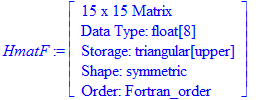
| > | HmatF:=Matrix(Hmat+0.001*Wmat,shape=symmetric); |
| > | convert(Eigenvalues(HmatF),list); |
![]()
![]()
![]()
We now assemble a table of eigenvalues for a graphical presentation of the energy levels as a function of field strength F . We applied trial and error to see what would be a reasonable field strength range.
| > | Np:=200: |
| > | for nu from 1 to Np do: |
| > | F:=0.0001*nu; HmatF:=Matrix(Hmat+F*Wmat,shape=symmetric); |
| > | FV[nu]:=F; EVal[nu]:=convert(Eigenvalues(HmatF),list); od: |
| > | plot([seq(seq([FV[nu],EVal[nu][i]],i=1..N),nu=1..Np)],style=point,view=[0..0.0001*Np,-0.55..0],title="Energy levels as a function of field strength F in atomic units"); |
![[Maple Plot]](images/StarkShift38.gif)
We observe at the level of n=2 a linear splitting of the eigenvalues for the two correct zeroth order eigenstates |2s>-|2p0> and |2s>+|2p0> respectively as derived in first-order degenerate perturbation theory.
The diagram illustrates the justification of first-order perturbation theory for weak fields: the two n=2,m=0 levels at first evolve with a large energy separation from the other levels. Energy denominators in second-order corrections suppress couplings. It is justified to ignore them in this regime and calculate the linear Stark effect in PT. Beyond F=0.002 atomic units this begins to be questionable, as an upper level is getting close. Eventually, with increasing field strength deviations from the linear behavior become quite apparent.
We can also notice the much stronger effect that the electric field has on the higher-lying states. At the n=3 level there are three states, because there are |3s>, |3p0>, |3d0> to be mixed.
The upward moving energy levels cross over into the E>0 regime at some coupling constant.
Level crossings (avoided crossings?) occur at strong fields. True level crossings involve a degeneracy which would be indicative of a symmetry in the Hamiltonian. Therefore, when a Hamiltonian depends on a parameter (such as F in our case) true level crossings should not occur when the parameter is varied. Levels can get very close but do repel each other to not become truly degenerate. Avoided level crossings play an important role in molecular phenomena and in slow ion-atom collisions. The character of a wavefunction (e.g., dipole moment) is usually maintained across the avoided crossing. For a system to follow its level as the parameter is changed, involves changing character. This will not happen when the parameter is varied rapidly: in this case the evolution follows by maintaining wavefunction shape and crossing the level. Diabatic energy level diagrams have allowed crossings, they do not represent solutions of the Schroedinger equation with parametric dependence, but reflect how the system evolves in real circumstances.
The ground state is not much affected for the field strength shown, because it sits deeply inside the potential barrier.
We learned from the treatment in parabolic coordinates that the calculated real energies are locations of resonances.
Exercise 2:
Select a field strength regime with an apparent energy level crossing which is isolated from the other neighbors (for example at F=0.003 the n=2 upper level meets one of the levels from above). Investigate this crossing by running the calculation on a fine F -grid, and by zooming in on this region in the graph. Do you find that the levels get close, but do not cross as is visible for some of the higher-level curve crossings?
Mini-Project:
Repeat the calculation with a Laguerre-type basis instead of the bound hydrogenic states. In this type of basis the exponential factor is fixed for all n -levels. Compare the convergence of a few low-lying eigenvalues at fixed field strength in this basis with the converged calculations in the hydrogenic bound-state basis. Describe and explain your observations.
| > |
| > |