This page is about programming ATMEGA328 chips, like the one found on the Arduino UNO, using modern (post 2015) tools like MPLAB X and the Snap or PICKit4 debuggers. As of July 2021 there is a little hiccup in how to do this. Hopefully in the future Microchip will fix the issue and render this page obsolete.
Introduction
The Arduino is arguably the most widely known microcontroller and C++ development platform on the planet. Shifting our first year programming curriculum to them during the COVID19 pandemic allowed students in all corners of the world to continue hands-on learning even when they couldn't attend school in person. The hardware is robust and flexible and the software is a joy to use compared to every other IDE I've ever used except IntelliJ.
That said, from an engineering or computer science perspective, the biggest downside to the Arduino is the lack of professional debug tools. This makes it a real challenge to integrate it into curriculum that emphasizes knowlege of computer architecture. The 8-bit ATMEGA328P at the heart of the Arduino UNO is a great chip to learn computer organization on. The instruction set is relatively small (almost as good as PIC16), setup is minimal (compared to MIPS, RISCV or ARM) and the chip is available in a throughhole package (like the PIC16, 24 and 32), making it breadboardable. But you can't access registers or memory directly on the UNO because the bootloader and the USB support chip block access.
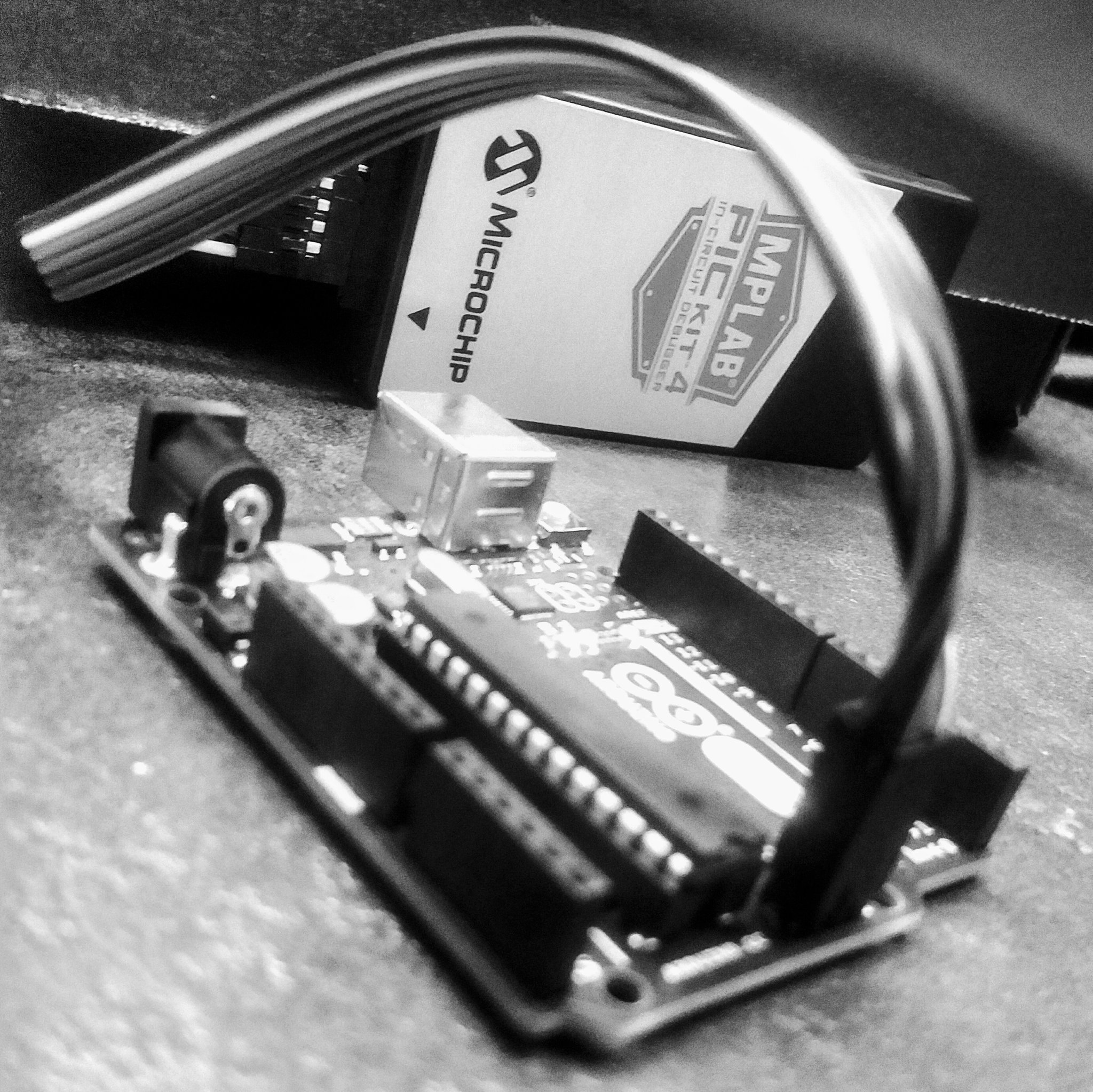
So, this page details what is necessary to allow the Arduino's ATMEGA328P chip to be accessed by a debugger. This is our main setup, as of Summer 2021:
- A Seeed Studio Grove Beginner Kit for Arduino
- A Snap debugger (as opposed to the more expensive PICKit 4)
- MPLAB X 5.35 or 5.50+ and XC8 compiler (skip 5.40... it's buggy)
Problem 1: Updated Snap firmwre needed
Due to a problem with the firmware set at the Microchip factory, the Snap must be reprogrammed before you can use it with the ATMEGA328. To that end you can either use a
- Breadboarded PIC16, or a
- Breadboarded PIC32.
Problem 2: Arduino UNO's need a hardware fix to allow debuggers / programmers
The Arduino UNO relies on a secondary chip to communicate over USB and to keep the internal bootloader happy. The secondary chip includes a "reset" connection to the ATMEGA328P chip that needs to be severed.
The original issue with the Snap
The Snap programmer is a great, low-cost programmer, but its factory-set firmware is designed only to work with the PIC chips out-of-the-box, not the ATMEGAs. If you try to program an ATMEGA with the Snap you'll be greeted with an error like this:
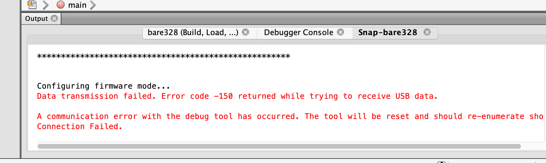
The problem with the Snap and ATMEGAs is well-known. The Microchip factory has been aware of it since at least December 2020. I reached out to Microchip in Spring 2021 to see if they could do something about it and got the "we'll think about it." In addition to the the firmware update approach described below, it could be that there is a hardware fix (with jumpers or soldering) but I don't know much more than that.
Honestly, Microchip should just reflash all the Snaps that they have in the factory and fix this silly problem.
Create a Project in MPLAB X
You'll need to create a stand-alone C project in MPLAB X. Inside the SRC folder of your project create a newmain.c file with this as the contents:
PRogramming PIC chips
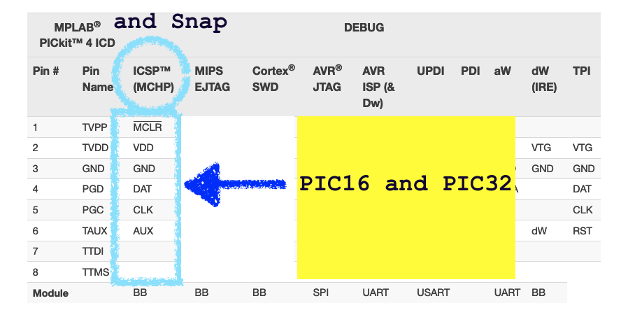
The Snap and PICKit4 are 8-pin updates to the 6-pin PICKit3 programmer. When you program PIC16 and PIC32 chips with the Snap or PICKit4 you use the first six pins and leave pins 7 and 8 unconnected:
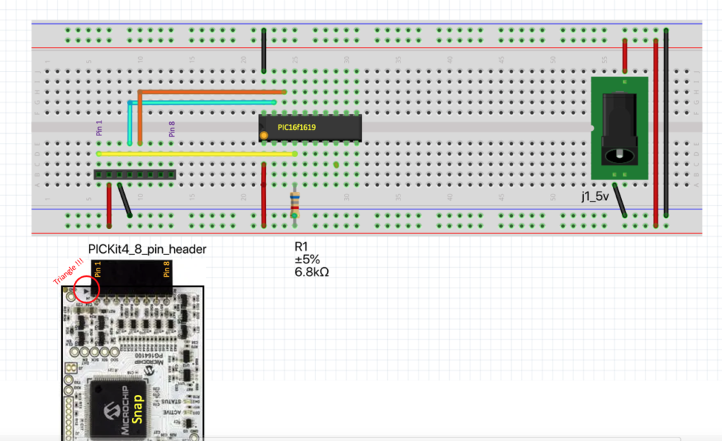
PIC Solution 1: PIC16
The PIC16 is a classic 8-bit processor family. The 'F1619 variant shown here is a modern "made for C" variant of the original PIC16F84 from the 1990s. While not popular in North American schools, it does have a large user base all over the world and I find it quite nice to develop with. The PIC16 circuit shown here is simpler and less expensive to set up than the PIC32 alternative.
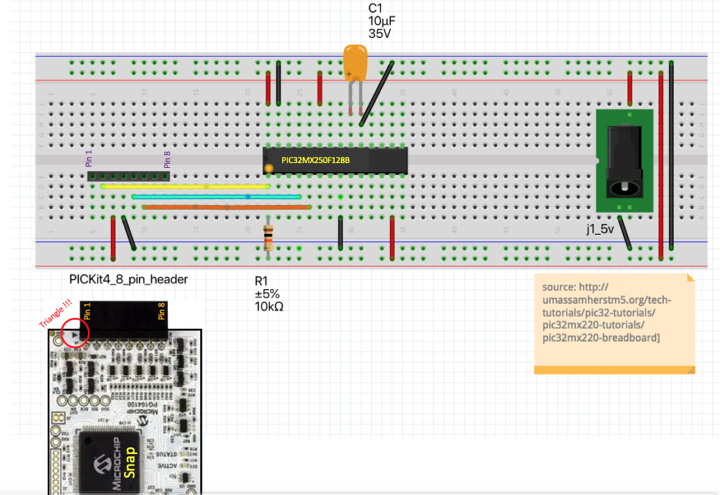
PIC Solution 2: PIC32
The PIC32 is the only 32-bit processor on the market that is breadboardable. I really like it. A simple PIC32MX breadboard setup is described in this basic circuit page. I set up my circuit using a PIC32MX250F128B. While the original page suggested a 10uF capacitor, I used a 1uF because that's all I had on hand. It worked. This is the breadboard circuit I used.
After the fix, program the ATMEGA
Now that you've reflashed the Snap, you can program the ATMEGA328 chip. In my case, I've tested this out on
- A bare ATMEGA328P chip in a breadboard
- An original Arduino UNO R3
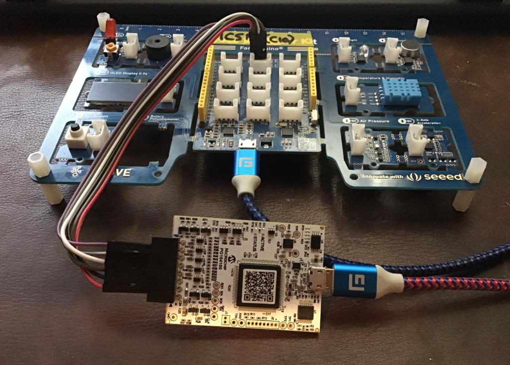
- A Seeed Studio Grove Beginner Kit for Arduino
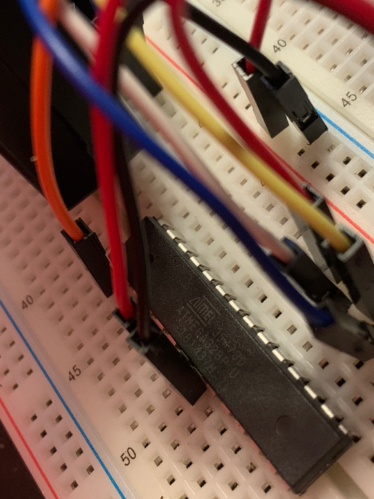
The Bare ATMEGA Chip on a Breadboard
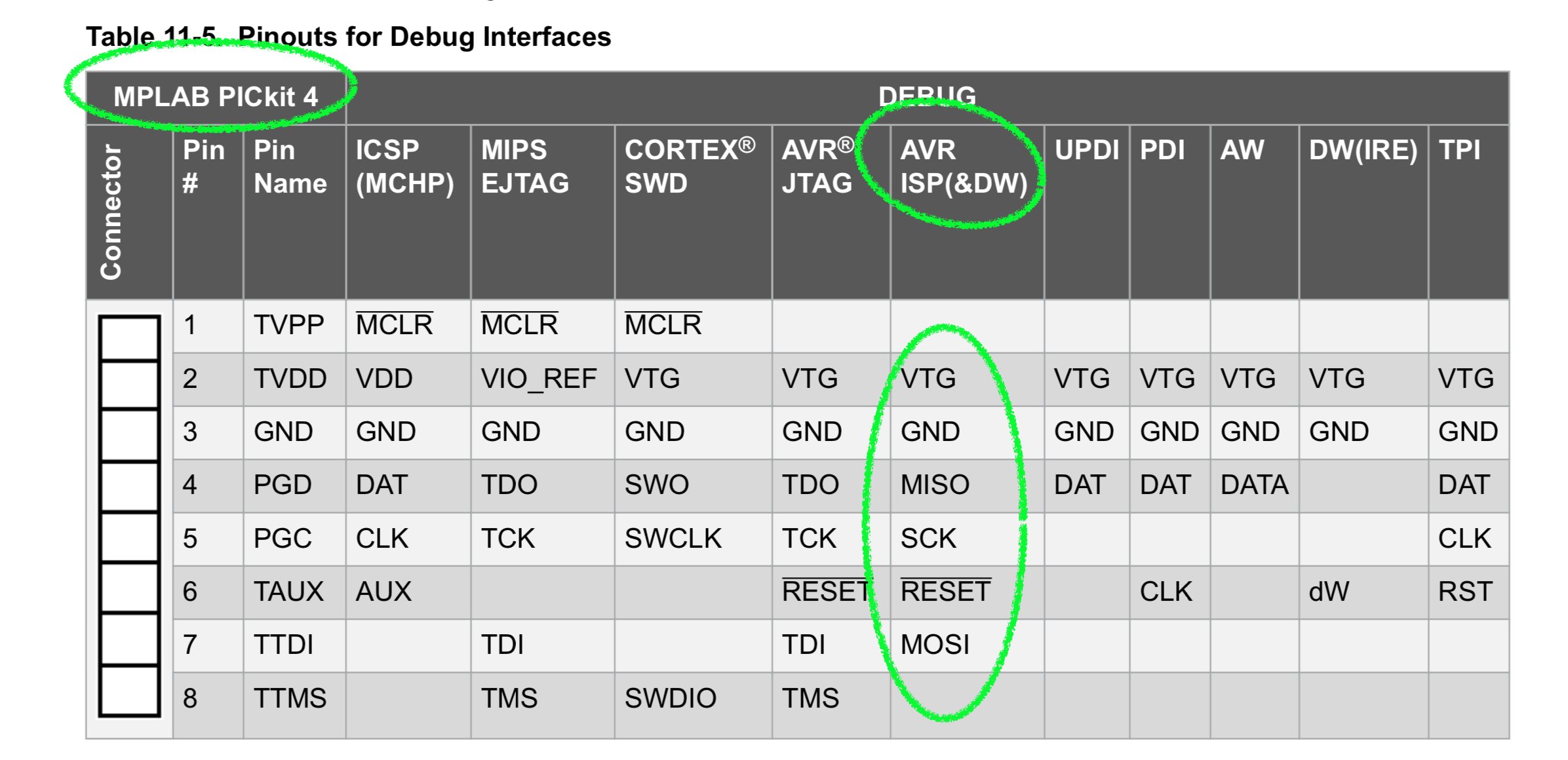
The ATMEGA328 connects to the Snap or PICKit4 programmers slightly differently than the PIC16 and PIC32 chips. The connections are based on the following pinout for either of the two programmers:
You can put together a really simple ATMEGA328 setup on a breadboard with minimal parts, including power and a header for the Snap or PICKit 4 programmer like this:
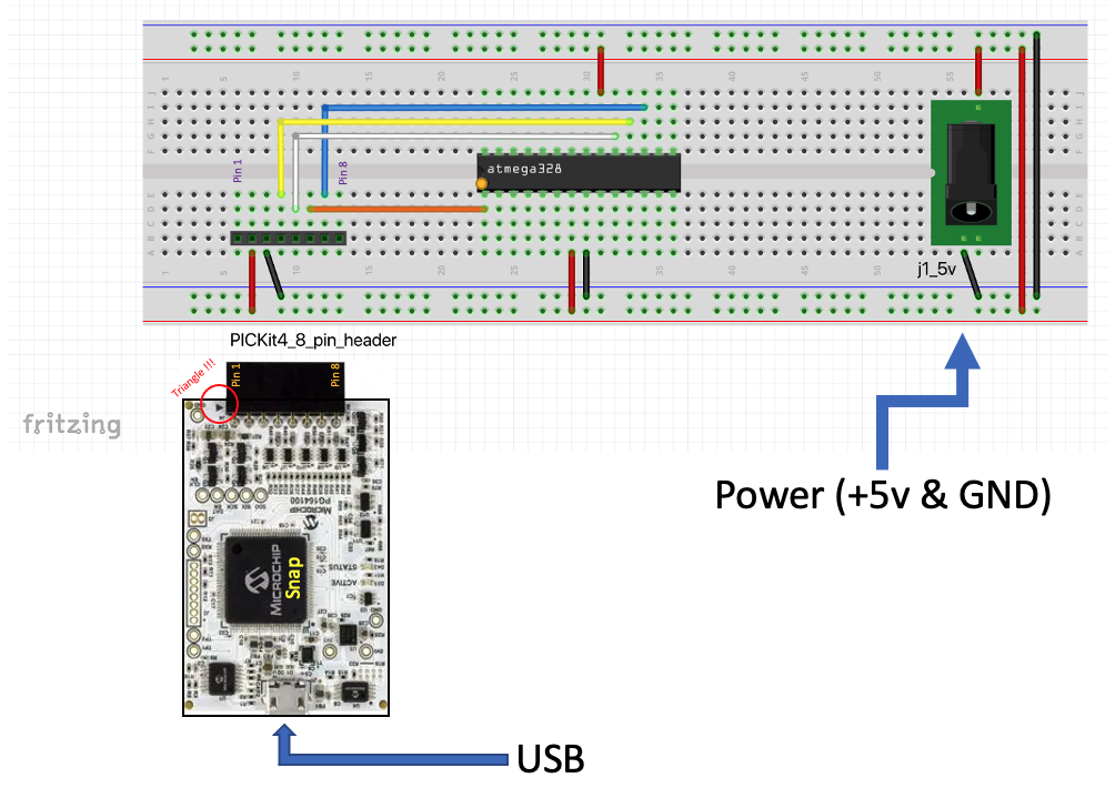
When programming the AVR, it's important to note that there are two distinct programming modes: ISP for simply writing programs to the chip and DebugWire which allows debug interactions between MPLAB X and the chip. More on this later.
Removing the reset line on the UNO or Seeed Kit
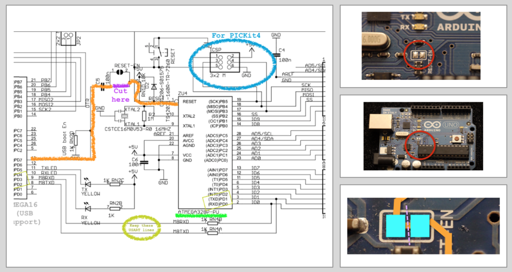
To allow Arduino-style boards with ATMEGA328P chips in them, like the Arduino UNO or the Seeed Studio Grove Beginner Kit for Arduino, you need to cut the reset line trace between the USB support chip and the ATMEGA328P. On the UNO relatively straight-forward as the trace is found between two solder pads and labelled "RESET_EN". Cut it using an X-acto stype knife, between the two solder pads:
A video overview of doing this on the UNO can be found here:
With boards like the Seeed Studio Grove Beginner Kit for Arduino, it's a little more challenging as the trace is not as easy to find. I found that simply removing capacitor C10 did the trick.
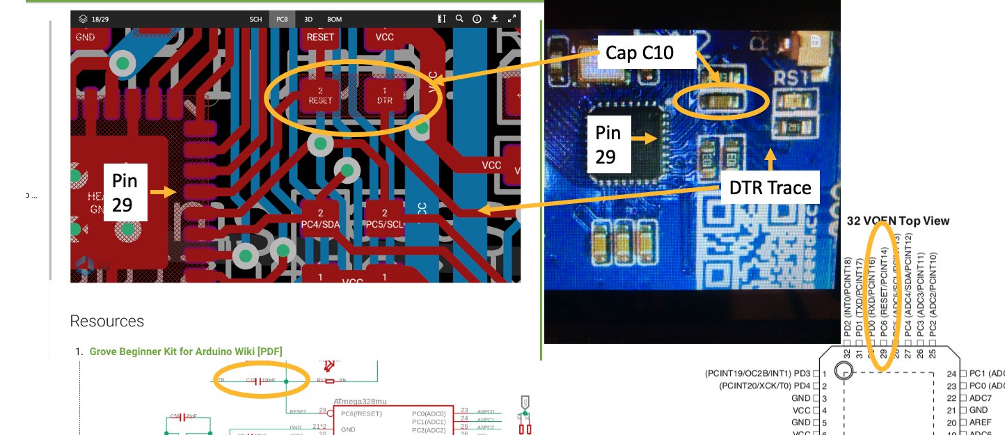
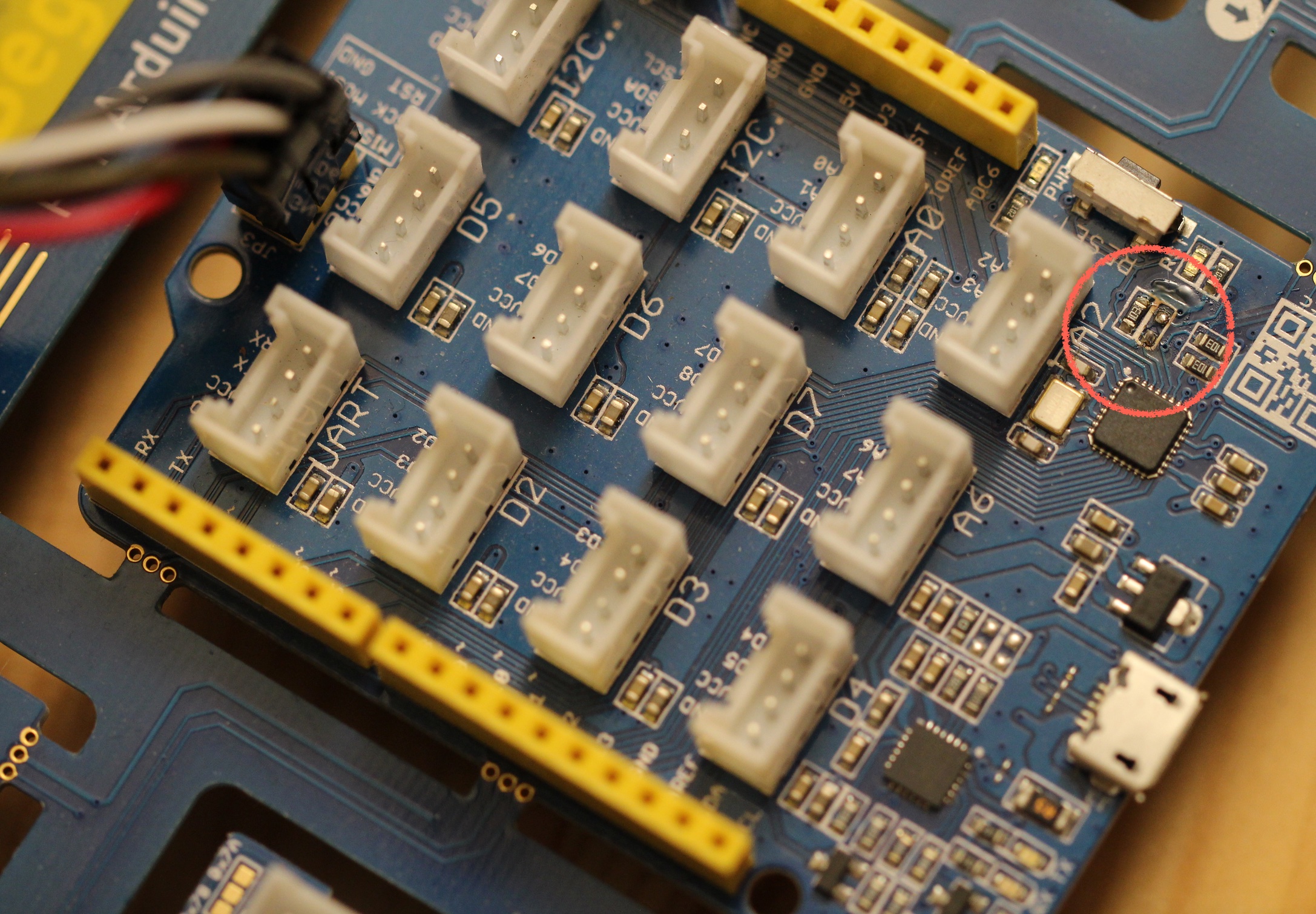
One way to remove the connection is to, on the Seeed board, remove capacitor C10 using a soldering iron (to melt it off) or pliers (to pry it off). The result looks like this:
Another way to deal with the reset line is to cut it like we did with the Arduino UNO. While I haven't done so myself, one of our talented technicians, Jaspal, has reported that cutting the reset trace nearest the FTDI ("USB Support") chip is the easiest way to do it.
The ICSP header on the UNO, Seeeduino or Seeed Grove Beginner Kit for Arduino
To program any ATMEGA328P-based Arduino-style device with a six pin ICSP (a.k.a. SPI) header you need to wire it up like this to the Snap or PICKit 4:
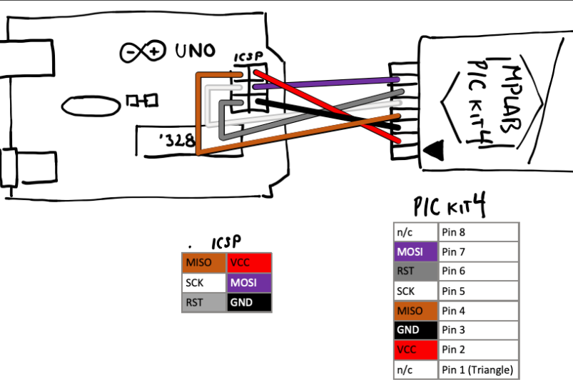
This connection is valid for boards like the ubiquitous UNO, but also for boards like the Seeed Studio Grove Beginner Kit for Arduino and many, many others.
Note that the programmers don't provide power to your board or chip. You need to provide power separately. That means that you typically have two USB cables connected: one to your programmer and one to the UNO (or equivalent) board. The one to the board provides power to the board. The one to the programmer allows reprogramming of the board to happen.
Programming the ATMEGA328 using MPLAB X: Switching between ISP and DebugWire modes
On my YouTube channel you'll find a number of example videos for setting up programs in MPLAB X. The setup for the ATMEGA328P is very similar to any other chip, whether it's the PIC16, SAMD or PIC32. Where it gets confusing is when you send the program to the chip and attempt to debug. That's because there are
- Two different programming modes (ISP and DebugWire)
- Two different ways that you need to set these modes (software and hardware)
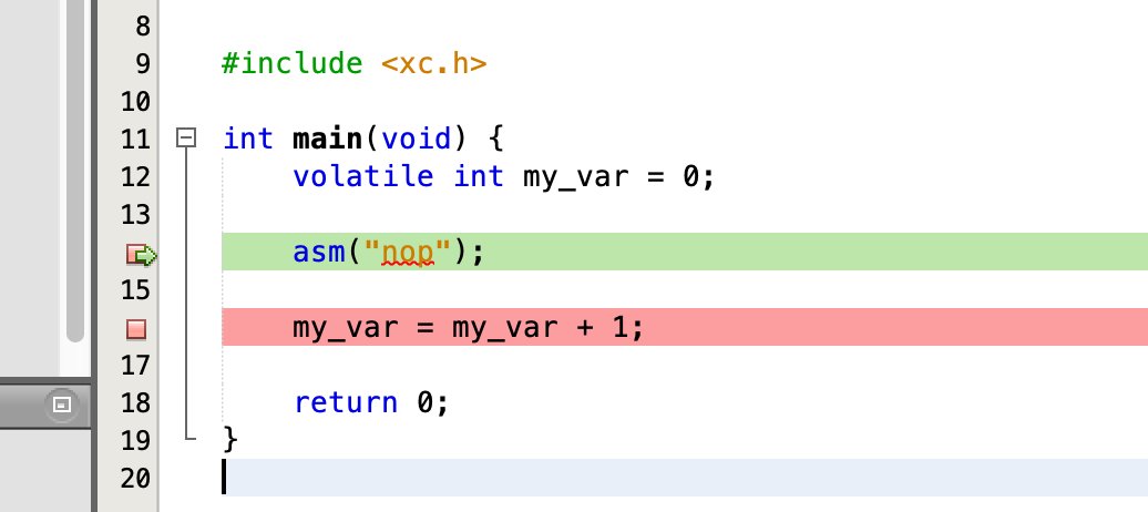
The chip typically is set to ISP mode when you get it, meaning that it is in program mode only and debugging is not allowed. Also, MPLAB X's project is likely in ISP mode initially. So, when you hit the "debug" button in MPLAB X, you're likely to encounter an error like this:
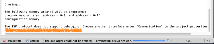
Select Project Properties, then either the "Snap" or "PICKit 4" option, then "Option Categories -> Communications" and then change from ISP to DebugWire. You can see the process here, about 8 minutes into the YouTube video.
Hit Debug again. Now, MPLAB X knows that you want to use the DebugWire protocol, but it'll detect that the chip is set to ISP mode. So it will prompt you to determine if you want the chip changed. Say yes.
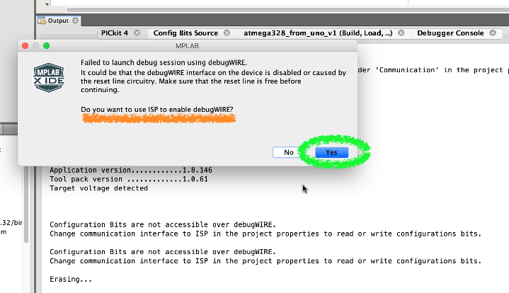
You may also be prompted to "toggle" power to the board or ATMEGA chip. Do it. That means unplugging and then plugging power to the board or chip. No need to disconnect to the PICKit 4 or Snap. Keep the programmer's USB cable plugged into the computer.
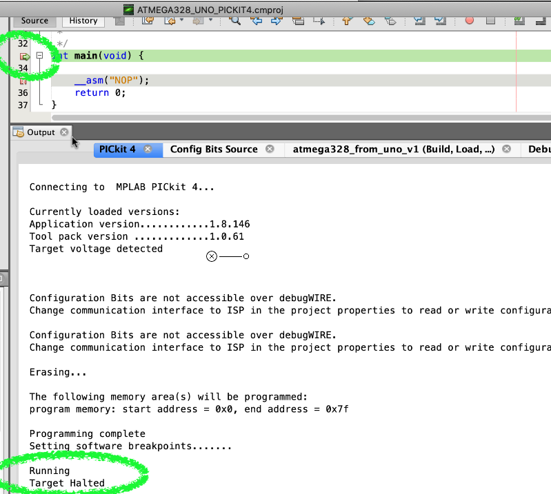
Hit the "Debug" icon again. Now, both MPLAB X and the chip should be in DebugWire mode and you should be able to send a program into the chip and, if you've set a breakpoint in MPLAB X, the program will halt and you can proceed with debugging your project.
Note
This post was originally a tweet from May 2021.
James Andrew Smith is an associate professor in Electrical Engineering and Computer Science Department in York University's Lassonde School. He lived in Strasbourg, France and taught at the INSA Strasbourg and Hochschule Karlsruhe while on sabbatical in 2018-19 with his wife and kids. Some of his other blog posts discuss the family's sabbatical year, from both personal and professional perspectives.