I'm getting set to teach a lab course at INSA Strasbourg in France, using PIC16 microcontrollers. My colleagues and I have made the decision to update the course from using the classic PIC16F84 to the more capable PIC16F1619. The '1619 is a bit more complex (a downside) but has debugging capability, like breakpoints (a big upside). The students are being exposed to Assembler on the '84 during their theory ("TD") class and to C on the '1619 during the lab ("TP") sessions. Even better, the '1619 Curiosity boards are cheap as dirt, making it practical for students to purchase for take-home practice, if they wish.
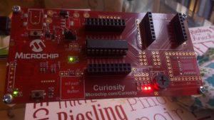
PIC16 Curiosity board with a PIC16f1619 chip on it.
One of the hidden complexities of this '1619 is the multiple uses that most of its pins can have. Case in point: The LED labelled D4 is connected to Port A, Bit 5 (i.e. RA5) on the PIC16F1619, shown in the figure below.
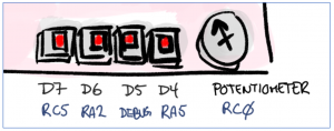
Closeup of the LEDs on the Curiosity board. The D7 and D6 LEDs, driven by Port bits RC5 and RA2 are easy to make work. The D5 LED is not available to the user. Meanwhile the D4 LED, driven by RA5, needs to be set up using "configuration bits" prior to usage.
Out of reset the chip normally assumes that there is a clock source connected to this pin, as is implied in the datasheet. That means that unless I can tell the pin that it doesn't have a clock attached to it it cannot be used to drive an LED. There is no normal register to tell it that. Unlike for the LED on RA2 (Port A, Bit 2), no amount of changing PORT, LATch or TRIState registers on Port A will change that. So what do you do?
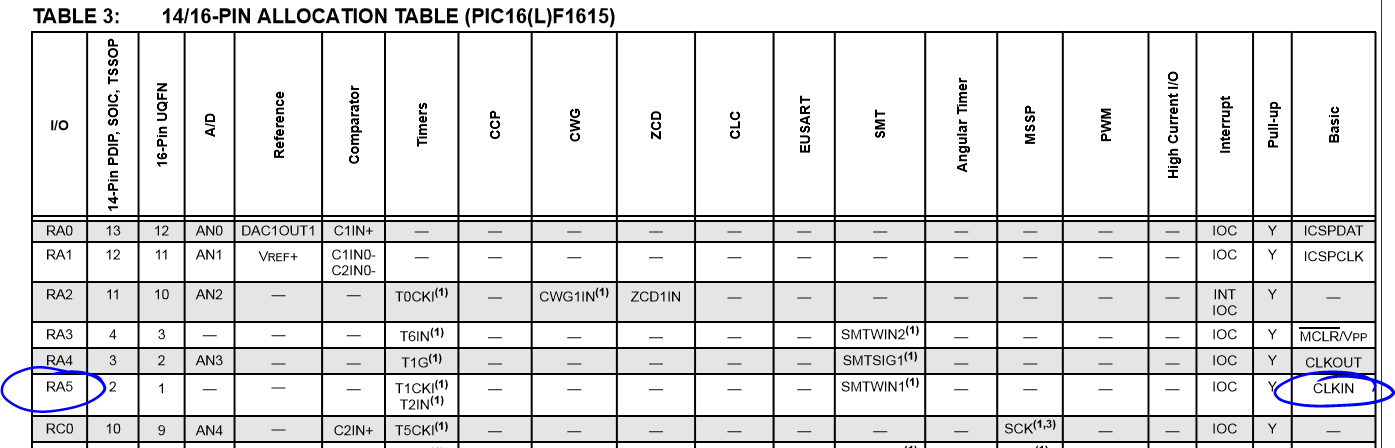
RA5 is assumed, be default, to be used as a Clock Input.
You need to use the "configuration registers", as described on the Microchip Developer page, and in this Stackexchange discussion. These settings can only be modified in the initial stages of programming the chip, using the debugger cable hardware. This requires the use of "#pragma config" statements that are used during the pre-processing stage of compilation. They cannot be modified inside your main() function or any usual part of your code. How you set this up isn't obvious, so using a built-in "wizard" is helpful, as shown below. You should also refer to the PIC16F1619 datasheet, starting on Page 60.
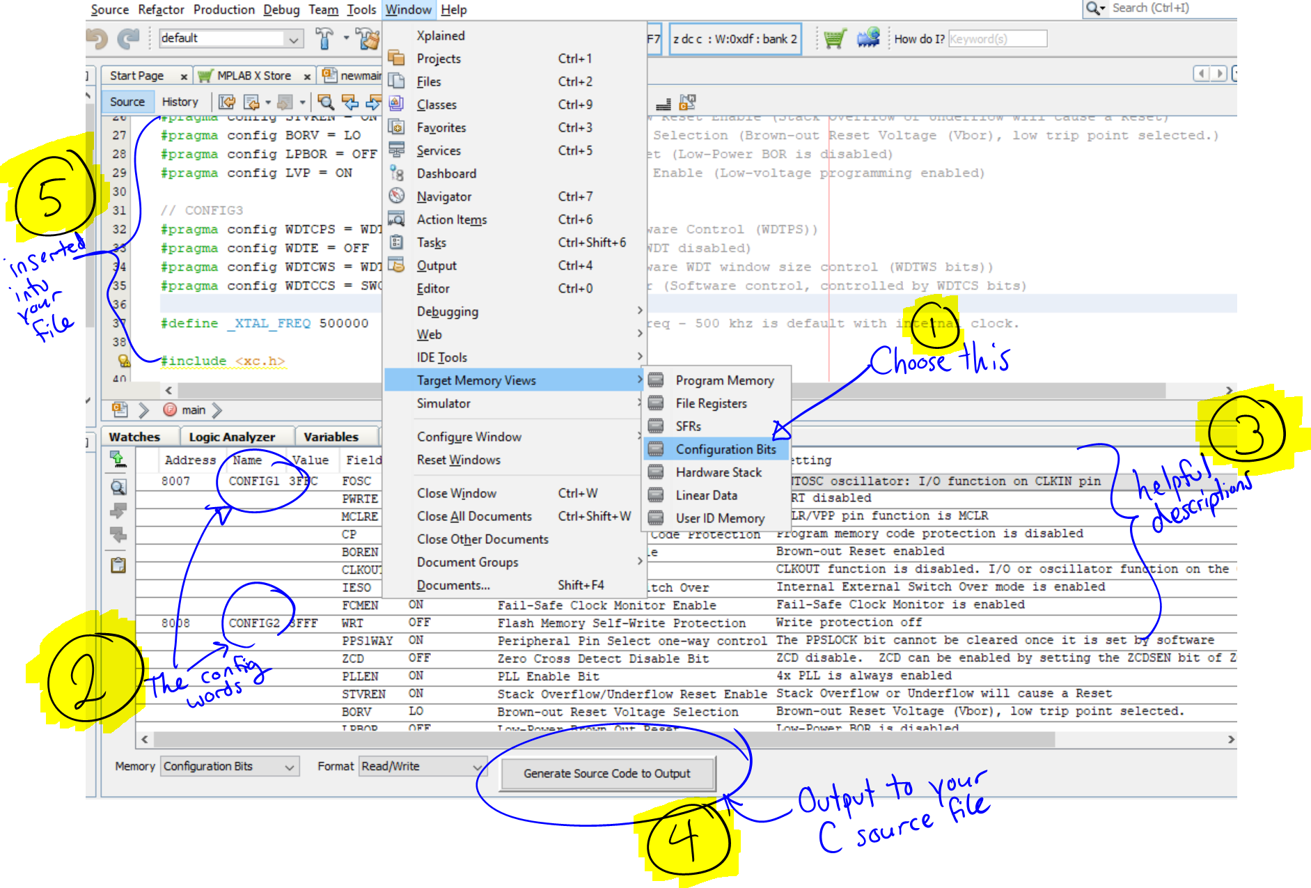
Using the configuration bit "wizard" to setup the special functions in the three configuration words of the PIC16F1619.
I used the default settings given to me by the wizard, but decided to rely on the "internal oscillator" as the main clock, thus requiring a modification to the FOSC configuration bit. This frees up RA5 to drive the LED. The following is the code generated by the wizard:
// CONFIG1
#pragma config FOSC = INTOSC // Oscillator Selection Bits (INTOSC oscillator: I/O function on CLKIN pin)
#pragma config PWRTE = OFF // Power-up Timer Enable (PWRT disabled)
#pragma config MCLRE = ON // MCLR Pin Function Select (MCLR/VPP pin function is MCLR)
#pragma config CP = OFF // Flash Program Memory Code Protection (Program memory code protection is disabled)
#pragma config BOREN = ON // Brown-out Reset Enable (Brown-out Reset enabled)
#pragma config CLKOUTEN = OFF // Clock Out Enable (CLKOUT function is disabled. I/O or oscillator function on the CLKOUT pin)
#pragma config IESO = ON // Internal/External Switch Over (Internal External Switch Over mode is enabled)
#pragma config FCMEN = ON // Fail-Safe Clock Monitor Enable (Fail-Safe Clock Monitor is enabled)

// CONFIG2
#pragma config WRT = OFF // Flash Memory Self-Write Protection (Write protection off)
#pragma config PPS1WAY = ON // Peripheral Pin Select one-way control (The PPSLOCK bit cannot be cleared once it is set by software)
#pragma config ZCD = OFF // Zero Cross Detect Disable Bit (ZCD disable. ZCD can be enabled by setting the ZCDSEN bit of ZCDCON)
#pragma config PLLEN = ON // PLL Enable Bit (4x PLL is always enabled)
#pragma config STVREN = ON // Stack Overflow/Underflow Reset Enable (Stack Overflow or Underflow will cause a Reset)
#pragma config BORV = LO // Brown-out Reset Voltage Selection (Brown-out Reset Voltage (Vbor), low trip point selected.)
#pragma config LPBOR = OFF // Low-Power Brown Out Reset (Low-Power BOR is disabled)
#pragma config LVP = ON // Low-Voltage Programming Enable (Low-voltage programming enabled)

// CONFIG3
#pragma config WDTCPS = WDTCPS1F// WDT Period Select (Software Control (WDTPS))
#pragma config WDTE = OFF // Watchdog Timer Enable (WDT disabled)
#pragma config WDTCWS = WDTCWSSW// WDT Window Select (Software WDT window size control (WDTWS bits))
#pragma config WDTCCS = SWC // WDT Input Clock Selector (Software control, controlled by WDTCS bits)
One last thing, between the #pragma statements and the main() function, I also define the frequency of the internal clock. It's 500 kHz. This is important to know for any timing-related function, including the basic "delay" function built into the xc8 compiler.
#define _XTAL_FREQ 500000 // Define PIC16F1619 clock freq - 500 kHz is default with internal clock.