Introduction
Here we're going to "kick the tires" on examining a simple example program, using three 8-bit microcontrollers: the classic PIC16F84A, it's updated cousin found on the Microchip Curiosity Board, the PIC16F1619, and the ATMEGA328P made famous by the Arduino UNO.
We'll be using a "debugging first" approach to programming that is intended to enable students to explore and self-learn with powerful, professional-grade and free (or really, really inexpensive) tools. (see Footnote 1)
The example will be done using MPLAB X and the XC8 compiler. We'll pretend that there is an LED attached to a pin on each microcontroller and write the C code with that in mind. Because the Arduino has an LED on Pin 13 of the board, and this board pin connects to Pin 19 on the ATMEGA328, we'll use it for this example. For the two PICs we'll use RA0, found on Pin 17 of the '84A and on Pin 19 of the '1619, as shown below.
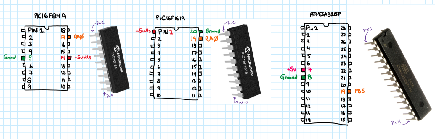
The three chips, the PIC16F84, the PIC16F1619 and the ATMEGA328 showing pins for +5 volts, ground and the digital signal pin on each chip that we'll work with.
Because this is an introductory tutorial and we don't want to get bogged down in issues related to actual hardware, we'll use the built-in simulator in MPLAB X to make-believe that we're using the real chip. This simulator allows you to examine things going on inside the chip in a way that can sometimes be hard to do in real hardware. It also allows you to get up-and-running really quickly and at no cost.
The program will fill registers in the microcontroller. When a register is filled with values it can do particular kinds of work. Different registers do different jobs. You can think of a computer register like an everyday cash register. You fill the bill slots with values and the display can display totals.
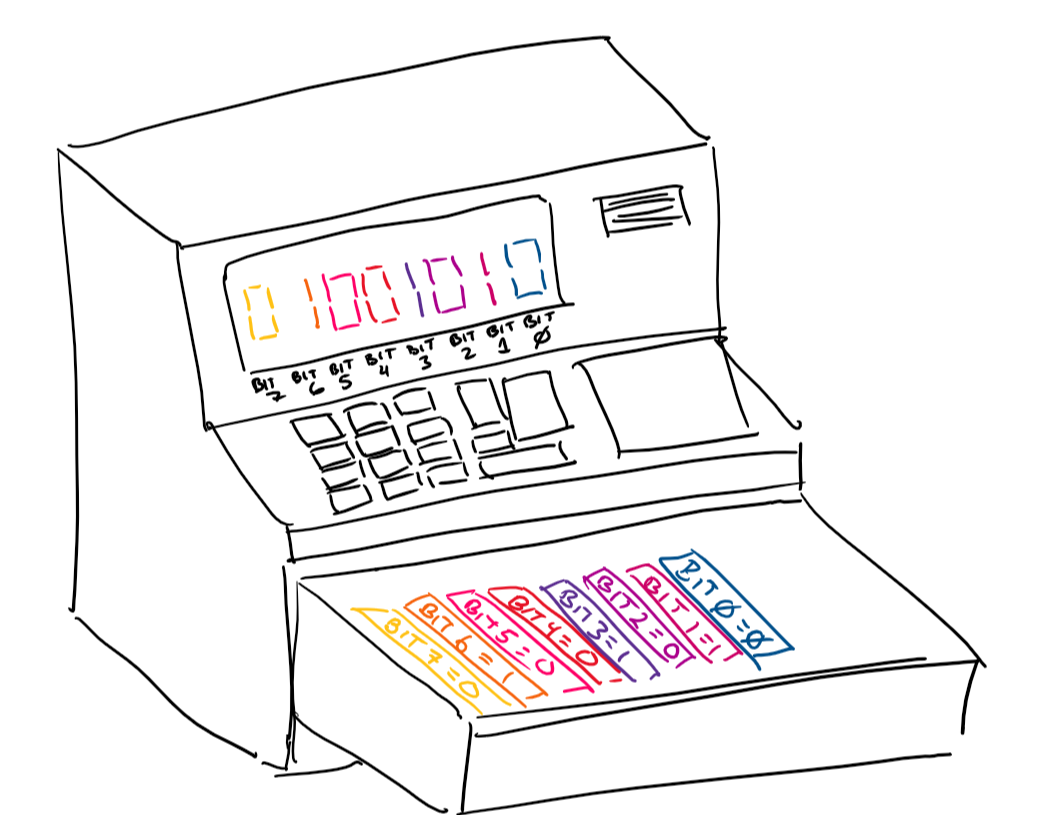
The cash register analogy of the computer registers. Each bill slot in the drawer corresponds to one digit on the display. Each bill slot either has one bill or no bills.
You've going to start a project in MPLAB X [add link to tutorial on starting a project] and select the PIC16F84A. Then, insert a newmain.c file in the sources part of your project. You will fill it will the following code.
#include <xc.h>
/* the main function. */
int main(int argc, char** argv)
{
TRISA = 0b00000000; // Make RA0 an output.PORTA = 0b00000001; // Make RA0 "logic high"
PORTA = 0b00000000; // Make RA0 "logic low"
return 0;
}
And it will look something like this in the MPLAB X editor.
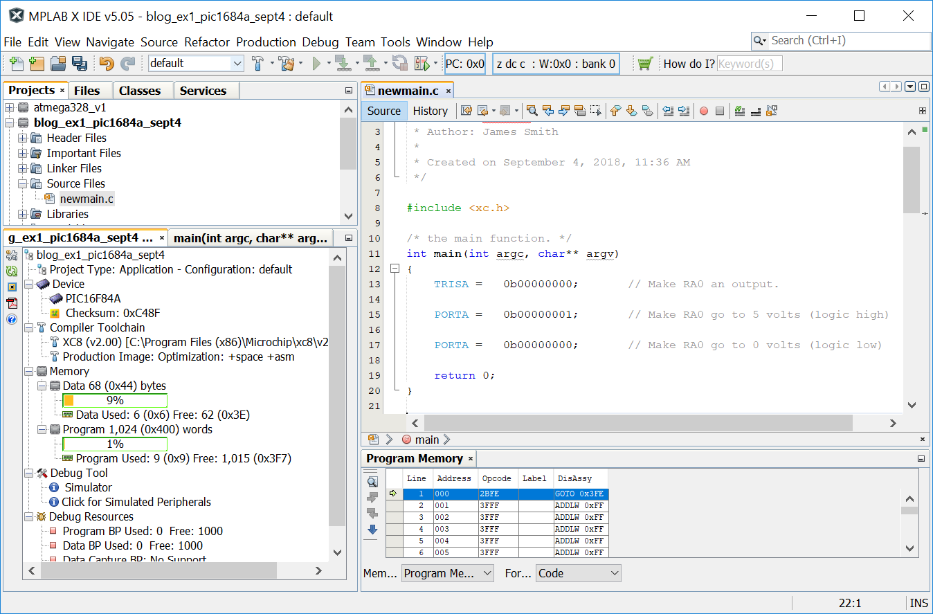
Example 1 with the PIC16F84A
Almost all of the action happens between the curly braces ("{" and "}") in the main function.
- The 8-bit TRISA register is fed an 8-bit binary number (0b00000000). This makes all of the pins in Port A change function to be "outputs."
- Next, using the PORTA assignment, the value of this output is set to 1 ("logic high") for the RA0 (Register for Port A, Pin 0) pin.
- Finally, using another PORTA assignment, the RA0 is set to logic low.
Now, if you've never looked at a binary number before, it begins with "0b" on the left, and then there are eight digits after that. Each digit can be either 0 or 1. When we set the TRISA register value, each binary digit corresponds to a particular pin on the microcontroller, as shown below.
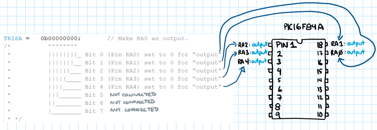
TRISA mapping to the PIC pins
In a similar fashion, setting the PORTA register's value will change the output voltage values on the RA pins.
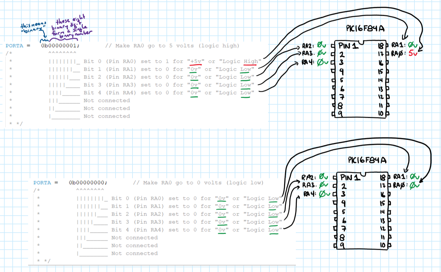
PORTA values set to first make RA0 5 volts, then set it to zero volts.
Now it's time to compile (hit the F11 key) and then simulate. Place a break point on the line number by TRISA. Then Window -> Debugging -> IO view and you should see this appear at the bottom of your screen:
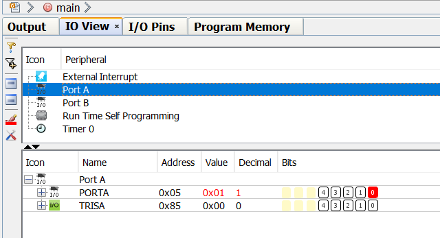
The I/O view in debugging mode (via Window->Debugging->I/O View)
Another handy perspective is the "I/O Pins" view. You get it through Window->Simulator->IOPin
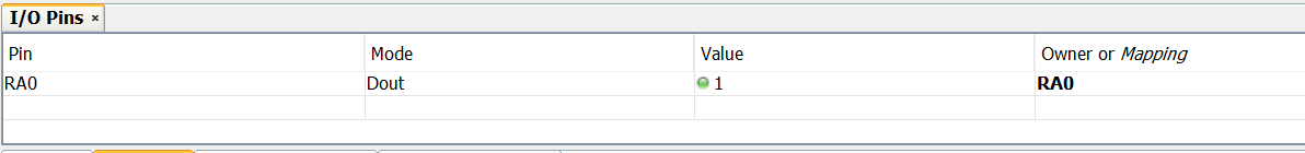
I/O Pin view via the Simulator set of views (via Window->Simulator->IOPin)
References
- PIC16F1619 datasheet & product page
- PIC16F84A datasheet & product page
- ATMEGA 328 datasheet & product page
Footnotes
Footnote 1: The "hello world" example made famous in the K&R C book is not conducive to a debugging-first approach to learning about microcontroller programming. While it's simple on a desktop or laptop computer, it's unnecessarily complex on a microcontroller due to the fact that most micros don't have a display and the code necessary for driving a display is complex (the complexity of the K&R C example is hidden by the use of libraries).