Introduction
This is the fifth in a series of twelve posts on recommended ways to assess learning outcomes in an engineering and computer science school whose programs follow the CEAB graduate attributes model of program characterization either directly or indirectly.
These posts are intended to be used as a guide for instructors to design assessments in their exams, lab activities, homework assignments and tutorials that can be deployed in a way that is measurable and meaningful both in terms of student assessment, but also in helping to frame data collection and analysis at a program level.
Background
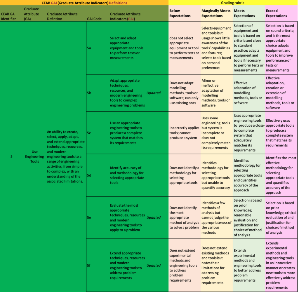
The 5th graduate attribute, Use Engineering Tools, can be broken down into six sub-categories, that we call "graduate attribute indicators":
- Select and adapt appropriate equipment and tools to perform tests or measurements
- Adapt appropriate techniques, resources, and modern engineering tools to complex engineering problems
- Use appropriate techniques, resources, and modern engineering tools to produce a complete system that matches its requirements
- Identify accuracy of and methodology for selecting appropriate techniques, resources and modern engineering tools
- Evaluate the most appropriate techniques, resources and modern engineering tools to apply to a problem
- Extend appropriate techniques, resources and modern engineering tools to address problem requirements
Here at York University we break down this main attribute into six sub-categories, but it's done differently at other schools. Six is a lot and we should probably reduce it to two or three subcategories, instead.
Each of these indicators can be measured at early, middle and late stages of a student's program. These stages correspond, roughly, to
- Years 1 and 2: Introductory
- Years 2 & 3: Developed
- Year 4: Applied or Advanced.
Of course, some electives in 4th year could be "Developed" or even "Introductory", depending on the topics and methods covered. Likewise, some courses in 2nd year may be introductory because the common engineering courses in 1st year don't necessarily cover specialized introductory topics in Civil or Space Engineering, for instance.
Assessments in this attribute are often lab- or project-based but can take place in exams, as well. The assessments can be quantitative in nature or can be qualitative. When examining these attributes qualitatively, consider using a rubric with four categories for assessment:
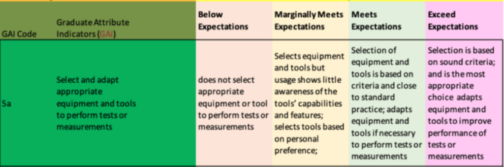
Example 1: "Select and adapt appropriate equipment and tools to perform tests or measurements" (5a)
Here are three examples, at each of the three program levels:
Introductory:
Question: In Lab F, you used a device to perform a measurement. Keep each answer to less than ten words. One point per question. No part marks. (a) What was it that your were measuring in Lab F? (b) What kind of device did you use to undertake the measurement? (c) What were the units of this measurement? (d) What range of values were you expecting to observe while performing your measurement?
Answer: (a) Voltage across a battery. (b) a Fluke multimeter (c) Volts (d) 0 to 20 Volts.
Grade: three out of three
Notes: The question was broken up into individual parts that allow for distinct but related pieces of knowledge to be expressed and assessed. This helps both you and the student during the assessment.
Developed:
Question: In Lab B, you were asked to measure voltage in a mixed signal circuit but were not told which tool to use. What tool(s) did you use to measure the voltage and why? Were there any significant adjustments were needed on any of your tools? You will be evaluated using the Rubric for GAI 5a, as shown below. Please note that in such a rubric-style of assessment, a score of 3/4 ("meeting expectations") is typical.
Answer: I used a standard analogue oscilloscope to measure the analogue signal voltage, both immediately after the DAC and after the amplification stage. However, on the digital input of the DAC I used a Logic Analyzer with I2C decoding capability.
Score: 3 out of 4: Meeting expectations, as per the rubric below. The student used the tools as expected.
Advanced:
Question: In your final project, (a) describe the equipment that you used to measure the performance of your system. (b) What were the criteria that led you to choose that equipment? and (c) if you had to adjust or adapt the measurement equipment to improve the measurements, why did you do so and why? If you did not, simply state that you did not. Note that you will be graded using the following rubric. Most students are expected to get "Meeting expectations" (numeric grade: 3 out of 4)
Answer: We used a Model XYZ logic analyzer to examine the serial data stream from our embedded microcontroller as it communicated with a sensors on over RS232. We chose the Model XYZ logic analyzer because it could capture low current digital signals with voltages from 0-3.3v at data rates of up to 20 MB/sec. Using the logic analyzer, we determined that the actual baud rate was within 2% of the desired value but we had to write a decoder script for the logic analyzer to automatically decode the packets as the included decoders were insufficient.
Grade: Student score: 4/4 ("exceed expectations") because the student met all the typical expectations and also wrote the optional custom decoder to aid in their analysis.
Notes: Use the rubrics to qualitatively evaluate the student answer. Give 0 for no answer, 1 for "Below expectations", 2 for "marginally meeting expectations", 3 for "meeting expectations" and 4 for "exceeding expectations". Don't give part marks. Ideally, most students will get 2 or 3. Few should get 4, otherwise your expectations should be recalibrated. Likewise if most students are getting 0 or 1, then a recalibration of the assessment or the formative material should be considered.
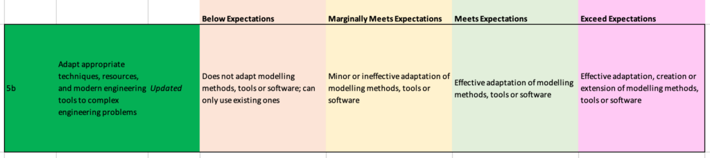
Example 2: "Adapt appropriate techniques, resources, and modern engineering tools to complex engineering problems" (5b)
There are two important key words here. First is "adapt". That's what the student should be doing -- adapting. Also note that what's "complex" for a typical 1st year student is not for a typical 4th year. Here are three examples, at each of the three program levels:
Introductory:
Question: In your programming project how did you test the validity of your Java method? You will be evaluated according to the rubric below.
Answer: I created a unit test using the JUnit library to examine three sample inputs and verified that the the output was, indeed, as expected.
Grade: 3 out of 4 (meeting expectations).
Notes: It's a 1st year programming course. The problem wasn't considered very difficult, while the testing inputs could have been more varied, what was important is that the student didn't just perform an ad-hoc test on a single input, they set up a test "jig" using the JUnit system. The JUnit system is just a library, and needs to be adapted for each individual case.
Developed:
Question: Modify the Verilog test program for the 4-bit circuit in Lab B to the 16-bit circuit illustrated here [illustration given]. A grade of 10 out of 10 will be assigned if the test program completes all ten standard tests for this circuit. A reduction of one point for each test missed or which results in an incorrect result will be applied, for a minimum score of 0.
Answer: Below are the Verilog source code and a screenshot of the successful execution of the test using iVerilog. [student provides source code and illustration.]
Score: 10/10. Student successfully executed all tests.
Note: No rubric was used here. We don't always need to use rubrics. Here, a grade is assigned which is proportional to the expected level and scope of work.
Advanced:
Question: In your capstone project, (a) describe the equipment that you used to measure the performance of your electromechanical system. (b) What were the criteria that led you to choose that equipment? and (c) if you had to adjust or adapt the measurement equipment to improve the measurements, why did you do so and why? If you did not, simply state that you did not. Note that you will be graded using the rubric above. Most students are expected to get "Meeting expectations" (numeric grade: 3 out of 4)
Answer: As our system was mobile we could not rely on a bench top data acquisition system. Instead, we integrated three off-the-shelf Arduino boards with an on-board SD Card to capture measurements on board. As per the requirements established in our earlier design report, we had to acquire 100 samples per second for a five minute test period, with voltages ranging from -5V to +5V at 10 bit resolution. We calibrated the system on the bench using a Model XYZ signal generator, using a Matlab test routine, as we learned to do in our 3rd year course, EECS 3456.
Grade: Student score: 4/4 ("exceed expectations") because the student met all the typical expectations, extended prior knowledge in doing so, but also created a new system that was not constrained in the way that their standard lab equipment was.
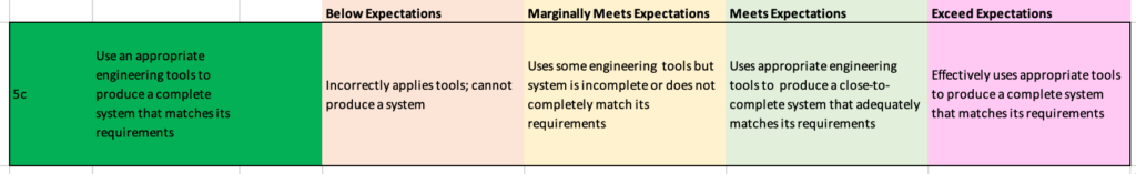
Example 3: "Use an appropriate engineering tools to produce a complete system that matches its requirements" (5c)
There are two important key terms here: "complete system" and "requirements".
Introductory:
Question: For your final project, have an LED flash at a fixed rate of 0.2 Hz using off-the-shelf parts. Grade is out of 10. If the system functions as required, you will get 8 out of 10. Partial functionality will result in half marks. Zero otherwise. Your final two marks will be granted if you successfully answer a skill-testing question about the Arduino hardware or the Matlab program that you developed. The questions are taken from a standard set provided, ahead of time, to the TA.
Answer: [the to TA, during a live demonstration] Here is my Arduino-based solution. It consists of an Arduino UNO and a prototyping board which includes a breadboard. The breadboard contains one LED and a 220 Ohm resistor. Here is my Matlab program which uses PWM to flash the LED at 0.2 Hz, which I can confirm using manual counting and a stop watch over a one minute period.
Grade: 10 / 10. TA verified and asked, live, the skill question on the PWM functionality in Matlab.
Notes: Off-the-shelf and basic programming. A skill question during a live demo, using a bank of questions is helpful as copying of programs such as this is typical.
Developed:
Question: For your final project, have an LED flash at a fixed rate of [rate is variable, based on student ID] Hz. Build the entire circuit on a breadboard, including a DIP package ATMEGA328 and internal oscillator. Writing the program using the Matlab or Arduino library will result in a "Marginally Meeting Expectations" result. If you are able to demonstrate your result to the TA and then can modify the program, live, to meet a new frequency specification stated by the TA, you will receive a "Meets Expectations" result. If you are able to do the same, but which a program completely written in Assembler, you will receive an "Exceeding Expectations" result.
Answer: [to the TA, during a live demonstration] Here is my Arduino-based solution on a breadboard. It flashes the LED at the rate required. No, I am not able to modify as per the TA request.
Score: Marginally meeting expectations (2 out of 4).
Advanced:
Question: For your final project, create a PCB which integrates an array of LEDs and an FPGA to create arbitrary image patterns at three different brightness levels, using PWM techniques. Provide a schematic, photo of your setup and a two minute video demonstration. Use the grading rubric above.
Answer: The student provides a finished PCB with all parts soldered to the board. Individual LEDS are shown to be functional using a Verilog program running on the FPGA.
Score: A score of 3 out of 4 is assigned as the student has a nearly completed system that almost meets the requirements. It's clear that, if given more time, the student would be able to write more complete Verilog code to better utilize the LED array.
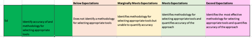
Example 4: "Identify accuracy of and methodology for selecting appropriate tools" (5d)
There are two important key terms here: "accuracy" and "methodology". It's in the context of tool selection.
Introductory:
Question: Select a microcontroller board capable of reading five volt analogue signals and that is compatible with Matlab. Grading is all-or-nothing: 1 for a completely correct solution. 0 otherwise.
Answer: I chose an Arduino UNO because its analogue inputs are 5-volt compatible and can be programmed using Matlab.
Grade: 1 out of 1.
Developed:
Question: Select a microcontroller chip capable of reading three volt analogue signals, but can also resolve the analogue signal to 12 bit levels at a rate of 500 khz. The chips should be in stock and should be less than $0.60 per unit, in bulk. Grading will be as per the rubric below.
Answer: I selected 15 models using the chip sector webpage at MyChipsAreAwesome.com. Of those, the five least expensive models were purchased and the accuracy of the ADCs of these models were tested using a program that I wrote, with values compared to the display on the signal generator. Four of the five units were found to meet the published specifications, within 1% of the generator, whereas the fifth unit was found to have a noisy ADC and its output was found to have an error of 5%.
Score: Three out of four. The method is sufficient to find good candidates but doesn't capture a very wide selection of parts beyond a single vendor.
Advanced:
Question: Select a radio module capable of decoding Amplitude Shift Keying signals for your final project. Determine a suitable methodology for component selection. You will be assessed using the rubric above.
Answer: We selected the Model XYZ receiver with an ABC front end. It was one of four units that met our budgetary requirements. Our selection methodology is a holistic one: supply-chain (manufacturer+distributor), performance, assembly and disposal (end of life) assessments. We made the selection after conducting an assessment of the manufacturer's historical and current stock levels -- an important consideration due to global shortages. We also examined its performance using a sample component using the test rig provided in the lab and found that the unit was able to meet our decoding accuracy requirements within 5% during a two hour bench top test. Finally, we assessed in-house assembly capability to determine if we could integrate it in the existing system, and we also assessed the ease with which we could dispose of the unit with an electronics recycler once we were finished with the prototype. The other three units examined all failed the performance or end-of-life components of the selection process.
Score: Four out of four (exceeding expectations) as the methodology went beyond just examining stock levels and pricing.
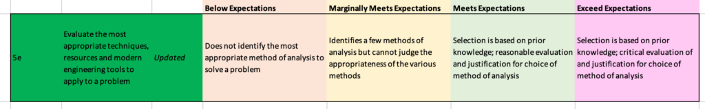
Example 5: "Evaluate the most appropriate techniques, resources and modern engineering tools to apply to a problem" (5e)
The important key term here: "most appropriate".
Introductory:
Question: Select a CAD program for simple mechanical designs for project boxes that can export results to a 3D printer. You will be evaluated using the rubric below.
Answer: I conducted a Google search and found a "top ten" list on CNET for CAD programs for 3D printers. I then chose AutoCAD because it got four stars on CNET.
Grade: Below Expectations (1 out of 4). The student chose an external review that had a general context, ignoring the analysis provided in the lab manual.
Developed:
Question: Select an ODE solver for the dynamics of the XYZ electrical circuit. Grading will be as per the rubric below.
Answer: I chose the ODE45 solver initially as it is a good general purpose solver. However, I observed gaps in the solution over multiple runs, and realized that I my system had a tighter accuracy than I had originally realized. For this reason I chose an ODE113 solver. It requires more time and computational resources, however.
Score: Three out of four. The student describes the justification in qualitative terms and is correct. However, the student could have gone further and compared differences quantitatively between the ODE113 and ODE45 (or other) solvers.
Advanced:
Question: Select a programming language for a fault-intolerant, hard real time embedded control system that does not have a traditional operating system such as Windows, Linux or macOS. You will be graded as per the rubric above.
Answer: After a brief web search and consultation with ChatGPT, our group compared four programming languages, microPython, C, C++ and Ada. We undertook a brief literature survey and contrasted our experiences in EECS 2345, EECS 3456 and EECS 4321 using C, C++, Java and Python. We did not have direct experience with either microPython or Ada and, therefore, filled in gaps using the literature survey. The result seemed to favour Ada, but there was significant disagreement within the team about our analysis of the literature and our personal experiences. For this reason, we decided to run short bench-marking LED flashing tests in all four languages. We were able to create the code for microPython, C and C++ by ourselves but required some assistance from ChatGPT for Ada due to our lack of experience. In C and C++ we were able to leverage both the PWM and DMA subsystems. We ran the benchmark test from class on all four languages, verifying response rates using both an external signal generator and logic analyzer with shared trigger signal. At a loop frequency of 10 Hz, all four systems performed within 1% of the target. However, when the control loop was increased to 100kHz, only the Ada-based system was found to maintain the 1% error rate.
Score: Four out of four (exceeding expectations) as the students realized a gap in their existing knowledge and chose to validate their assumptions objectively.
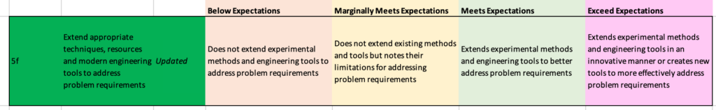
Example 6: "Extend appropriate techniques, resources and modern engineering tools to address problem requirements" (5f)
The important key term here: "extend". Also note the use of the term "experimental" as one avenue that can be pursued.
Introductory:
Question: Use a CAD program and a 3D printer to create a project box, with a lid. You will be evaluated using the rubric below.
Answer: Using AutoCAD and a MakerBot 3D printer, I created a project box but realized that I wanted to have the lid attach permanently to the box but could not make a joint for the lid, so I purchased one from Home Depot and added it to the finished product
Grade: Exceeding Expectations (4 out of 4).
Developed:
Question: Use a CAD program and a 3D printer to create a project box that does not suffer from the permeability issue that is typical of addictive manufacturing techniques. You will be evaluated using the rubric below.
Answer: Using SolidWorks and a MakerBot 3D printer, I created a project box, but realized that the resulting box was too permeable. So I modified the design to include O-rings and used a heat gun with spreader to refinish the inside and outside surfaces.
Score: Two additional methods were applied to address the permeability problem.
Advanced:
Question: The Firmata firmware permits a microcontroller to be controller remotely from a PC but the commuincaiton rate is too slow for the type of control application envisioned in the final project. Modify the firmware as well as the client software to increase the communication rate to 5 MB/sec. You will be evaluated using the rubric below.
Answer: I modified the firmware from within the Arduino IDE to increase the communication rate from the "server" side. From the client side I modified the java library to both increase the communication frequency but also enabled asynchronous packet transmission and reception. Using a logic analyzer I confirmed the new communication rate was functioning within 4% of the desired rate. A baseline project was compared at both old and new rates and the external behaviour (LED flashing and motor turning) was found to be qualitatively identical.
Score: Three out of four (meeting expectations) as the students realized a gap in their existing knowledge and chose to validate their assumptions objectively.
James Andrew Smith is a Professional Engineer and Associate Professor in the Electrical Engineering and Computer Science Department of York University's Lassonde School, with degrees in Electrical and Mechanical Engineering from the University of Alberta and McGill University. Previously a program director in biomedical engineering, his research background spans robotics, locomotion, human birth and engineering education. While on sabbatical in 2018-19 with his wife and kids he lived in Strasbourg, France and he taught at the INSA Strasbourg and Hochschule Karlsruhe and wrote about his personal and professional perspectives. James is a proponent of using social media to advocate for justice, equity, diversity and inclusion as well as evidence-based applications of research in the public sphere. You can find him on Twitter. Originally from Québec City, he now lives in Toronto, Canada.